A Method for Measuring Pressure Relief Range of Protective Layer Mining with Multiple Borehole Information

A technology of protective layer and protected layer, which is applied in the direction of earthwork drilling, mining equipment, instruments, etc., can solve the problems of less drilling information, difficulty in obtaining, and inability to take into account, so as to ensure authenticity and objectivity, avoid The effect of pressure relief dead zone

Active Publication Date: 2018-11-23
HUNAN UNIV OF SCI & TECH
View PDF4 Cites 0 Cited by
  • Summary
  • Abstract
  • Description
  • Claims
  • Application Information

AI Technical Summary

Problems solved by technology

[0002] The mining of protective layers is the preferred regional outburst prevention measure for the control of gas disasters in outburst mines. Although the "Regulations on the Prevention and Control of Coal and Gas Outbursts" provide a theoretical reference boundary line for the determination of the pressure relief range of the protected layer, it is required that the mining process of the protective layer In the first working face, the actual boundary line of the pressure relief range must be measured. In the past, due to the small amount of measured drilling information, it was difficult to obtain the real boundary line of the pressure relief range, especially in the strike length. On a long working face, some pressure relief blind areas often appear and people mistakenly think that the pressure relief is completed. Although there is an investigation on the pressure relief effect, it is impossible to take into account each smaller area.

Method used


Image

  • A Method for Measuring Pressure Relief Range of Protective Layer Mining with Multiple Borehole Information
  • A Method for Measuring Pressure Relief Range of Protective Layer Mining with Multiple Borehole Information
  • A Method for Measuring Pressure Relief Range of Protective Layer Mining with Multiple Borehole Information

Examples


Embodiment Construction

[0024] The present invention will be further described below in conjunction with the accompanying drawings.

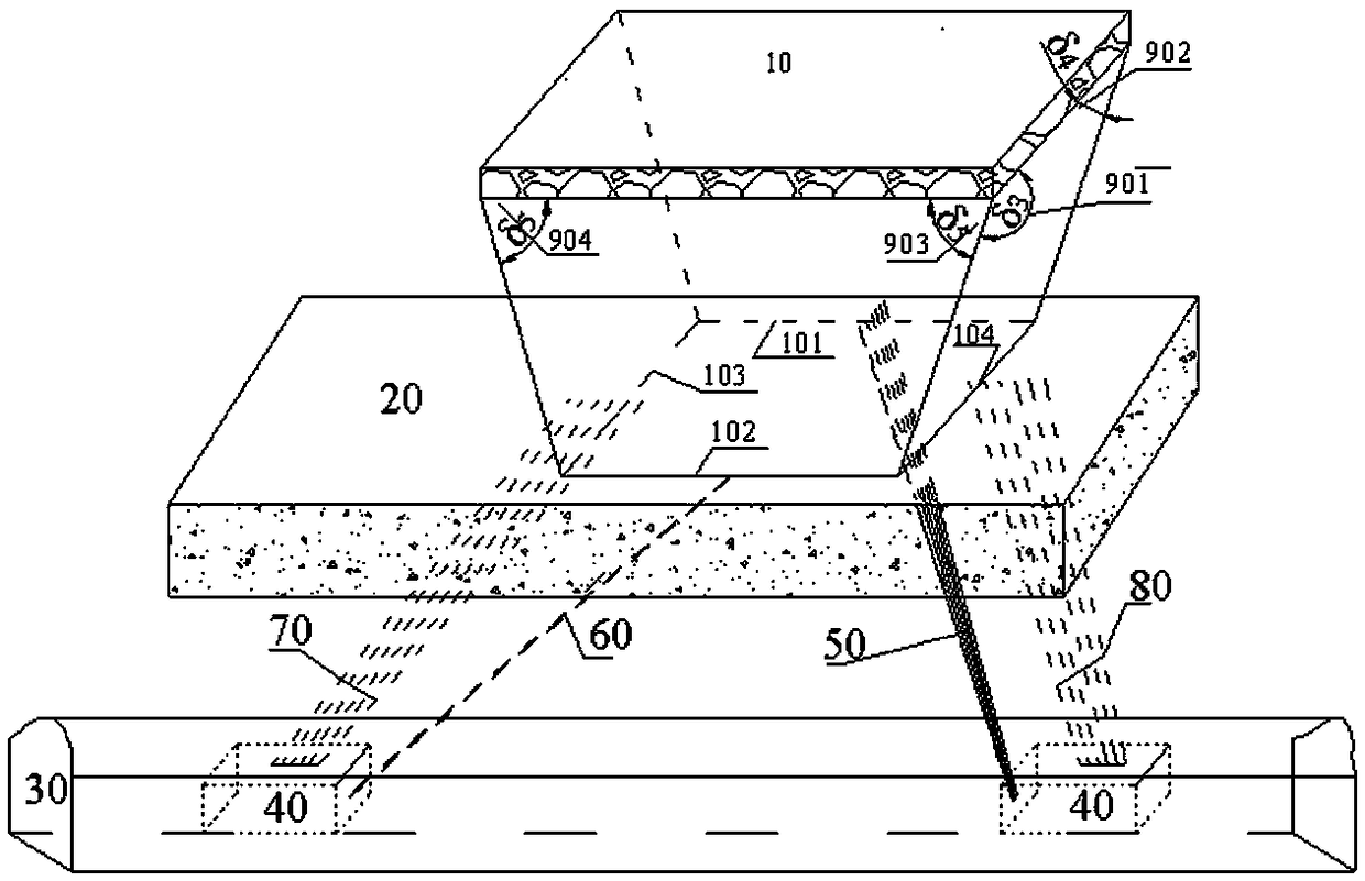
[0025] Such as figure 1 As shown, whether the mining of the protective layer 10 can effectively relieve pressure on the protected layer 20 depends on the occurrence dip of the coal seam itself and the vertical distance between the protective layer 10 and the protected layer 20. If the distance between the protective layer 10 and the protected layer 20 If the vertical distance exceeds the maximum protective vertical distance range between the protective layer and the protected layer specified in the "Regulations on the Prevention and Control of Coal and Gas Outburst" (the upper protective layer: the steeply inclined coal seam is less than 60m, and the gently inclined and inclined coal seam is less than 50m), then the protective layer is 10 Mining cannot affect the pressure relief of the protected layer 20, that is, the pressure relief effect cannot be achieved, and the ...


PUM


Abstract

The invention discloses a multi-borehole information protecting layer mining pressure relief range actual measurement method which includes the steps: 1) drawing a protecting layer mining stereoscopic schematic diagram and drawing theoretical reference boundary lines in the protecting layer mining stereoscopic schematic diagram; 2) designing a special gas extraction lane and a drill site; 3) designing actual measurement boreholes; 4) constructing the actual measurement boreholes; 5) recording borehole information; 6) calibrating an actual measurement pressure relief range. Authenticity and objectivity of the influence range of protecting layer mining for protected layer pressure relief are fundamentally guaranteed, protecting layer mining actual pressure relief range can be acquired, pressure relief blind zones are avoided, and powerful technical support is provided for safe and efficient mining of a protected layer.

Description

technical field [0001] The invention belongs to the field of mine gas prevention and control, and in particular relates to a method for measuring the pressure relief range of protective layer mining with multi-drilling information. technical background [0002] The mining of protective layers is the preferred regional outburst prevention measure for the control of gas disasters in outburst mines. Although the "Regulations on the Prevention and Control of Coal and Gas Outbursts" provide a theoretical reference boundary line for the determination of the pressure relief range of the protected layer, it is required that the mining process of the protective layer In the first working face, the actual boundary line of the pressure relief range must be measured. In the past, due to the small amount of measured drilling information, it was difficult to obtain the real boundary line of the pressure relief range, especially in the strike length. On a long working face, there are often...

Claims


Application Information

Patent Timeline
Patent Type & Authority Patents(China)
IPC IPC(8): E21F7/00G06F17/50
CPCE21F7/00G06F30/20
Inventor 罗文柯施式亮
Owner HUNAN UNIV OF SCI & TECH
Why Eureka
Try Eureka