Shearing seepage box for full shearing-seepage coupling test for rock joint under high permeability pressure

A technology of rock joints and high permeability, which is applied in the fields of permeability/surface area analysis, measuring device, suspension and porous material analysis, etc. It can solve the problems of poor sealing effect, inability to achieve sealing effect, and low accuracy of test results, etc., and achieve good results. simulated effect

Active Publication Date: 2017-05-31
TONGJI UNIV +1
View PDF9 Cites 14 Cited by
  • Summary
  • Abstract
  • Description
  • Claims
  • Application Information

AI Technical Summary

Problems solved by technology

At present, there are only a few test equipments on the shear-seepage coupling characteristics of rock joints in China. Due to the sealing technology and design defects of the shear seepage box, the shear seepage of rock joints in the actual test process has poor sealing effect and test results. In the case of poor precision (excessive friction of the shear cell system), a good seal cannot be achieved, especially at high osmotic pressures

Method used


Image

  • Shearing seepage box for full shearing-seepage coupling test for rock joint under high permeability pressure
  • Shearing seepage box for full shearing-seepage coupling test for rock joint under high permeability pressure
  • Shearing seepage box for full shearing-seepage coupling test for rock joint under high permeability pressure

Examples


Embodiment 1

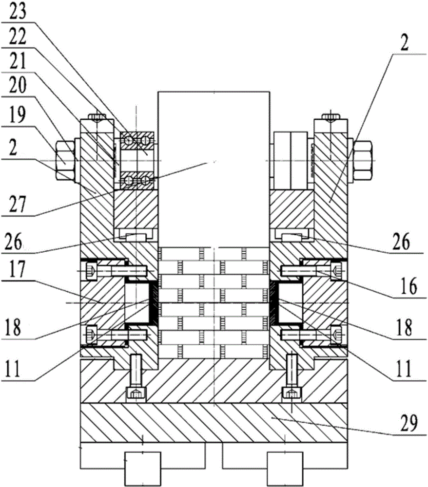
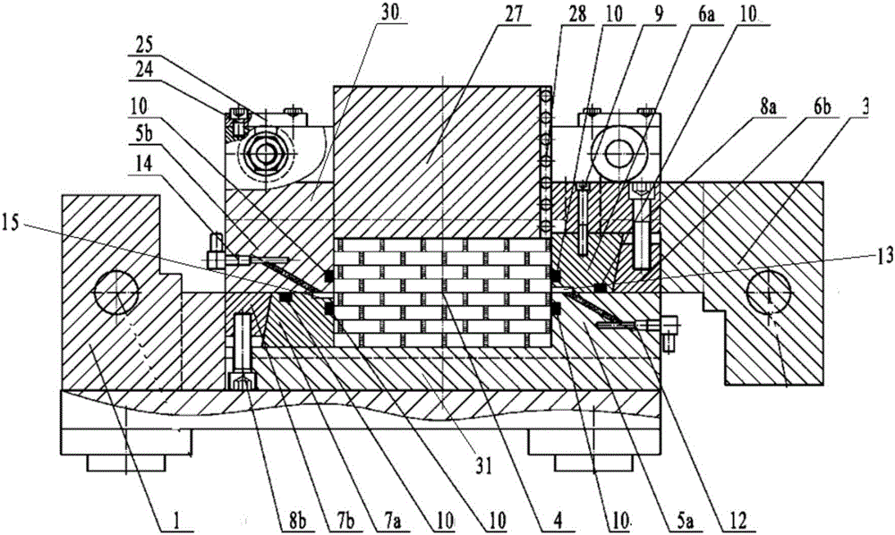
[0033] A full shear-seepage coupling test shear seepage box for rock joints under high permeability pressure, such as figure 1 with figure 2 As shown, it includes a lower shear box 1, two side plates 2 which are arranged on both sides of the lower shear box 1 and are vertically fixed to the lower shear box by hexagon socket screws, and an upper shear box 3. The lower shear box 1, the two side plates 2 and the upper shear box 3 form a cavity for placing the rock sample 4, and upper fixed shear blocks 5a for fixing the rock sample 4 are provided at both ends of the cavity. Lower fixed shear block 5b and No. 1 upper wedge cut block 6a, No. 2 upper wedge cut block 6b, No. 1 lower wedge cut block 7a and No. 2 lower wedge cut block 7b that can be horizontally displaced; The fixed cut block 5a, the lower cut box 1 and the lower bottom plate 31 are processed into a whole, and the upper fixed cut block 5b, the upper cut box 3 and the upper top plate 30 are processed into a whole. The N...


PUM


Abstract

The invention relates to a shearing seepage box for a full shearing-seepage coupling test for a rock joint under high permeability pressure. The shearing seepage box comprises an upper box body, a lower box body, lateral plates, a bearing platform and a normal loading cushion block, wherein the upper box body and the lower box body are used for accommodating a rock sample; the lateral plates are arranged on the two sides along the width direction of the rock sample; the bearing platform is arranged at the bottom of the lower box body; the normal loading cushion block is pressed on the rock sample; the upper box body, the lower box body and the lateral plates are jointly formed into a chamber for accommodating the rock sample; the lower box body is fixed with the lateral plates through bolts; a straight rail is arranged on the middle parts of the lateral plates; the upper box body is placed on the straight rail; a water entering channel which is communicated with the chamber is arranged in the upper box body; a water draining channel which is communicated with the chamber is arranged in the lower box body. Compared with the prior art, the invention has the advantages that the test condition is more approximate to a true seepage condition of the rock in the engineering, the sealing in the shearing process of the rock joint sample can be effectively realized, high permeability water pressure can be endured, the test precision is high and the full shearing-seepage coupling test for the rock joint under natural state can be more effectively simulated.

Description

Technical field [0001] The present invention relates to a shear box and a test method, in particular to a shear seepage box for a full shear-seepage coupling test of rock joints under high permeability pressure. Background technique [0002] Deep underground engineering mainly involves nuclear waste disposal, underground natural gas storage, deep mining, CO 2 Storage, geothermal development and compressed gas energy storage cover various fields of national economy and people's livelihood. In deep underground engineering with rich water, joint fissures often have high-velocity seepage and rock mass stability problems caused by high permeability difference and high hydraulic gradient. On the one hand, the engineering stability of deep rock masses largely depends on the seepage characteristics of the joints. On the other hand, the changes in stress in the deep rock masses, especially the effect of shear stress, cause the joints to open or close and deform and cause the seepage chara...

Claims


Application Information

Patent Timeline
Patent Type & Authority Applications(China)
IPC IPC(8): G01N15/08
CPCG01N15/08
Inventor 夏才初钱鑫桂洋黄曼江山张亮庄小清喻强锋
Owner TONGJI UNIV
Why Eureka
Try Eureka