Auto-collimating telescope barrel

A telescope and self-collimation technology, applied in the field of experimental instruments, achieves the effects of low cost, easy and quick adjustment, and convenient operation

Inactive Publication Date: 2017-05-31
JIANGNAN UNIV
View PDF4 Cites 0 Cited by
  • Summary
  • Abstract
  • Description
  • Claims
  • Application Information

AI Technical Summary

Problems solved by technology

[0004] Aiming at the present situation, the present invention can solve the problems encountered in adjusting the spectrometer at present

Method used


Image

  • Auto-collimating telescope barrel
  • Auto-collimating telescope barrel

Examples


Embodiment Construction

[0010] Below in conjunction with accompanying drawing, the present invention is described in further detail:

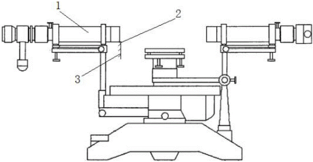
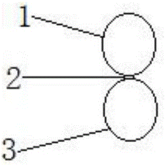
[0011] like figure 1 , figure 2 Shown, a self-collimating telescope barrel of the present invention comprises a self-collimating telescope barrel 1, a pin shaft 2, and a plane mirror 3. It is characterized in that: the lower right end of the self-collimating telescope barrel 1 and the upper end of the plane mirror 3 It is connected through the rotation of the pin shaft 2, and it is satisfied that when the plane mirror 3 is rotated 180° to the right, the mirror surface of the plane mirror 3 is perpendicular to the self-collimating telescope barrel 1, and the diameter of the plane mirror 3 is equal to the outer diameter of the self-collimating telescope barrel. .

[0012] When in use, turn on the small light in the telescope barrel, rotate the eyepiece focusing handwheel on the left end of the telescope barrel, see the fork wire on the reticle, and turn the plane mir...


PUM


Abstract

The invention discloses an auto-collimating telescope barrel. The auto-collimating telescope barrel comprises an auto-collimating telescope barrel body, a hinge pin and a plane mirror and is characterized in that the right lower side of the auto-collimating telescope barrel body is in rotational connection with the upper end of the plane mirror through the hinge pin, and when the plane mirror rotates rightwards by 180 degrees, a mirror plane of the plane mirror is perpendicular to the auto-collimating telescope barrel body, and the diameter of the plane mirror is equal to the external diameter of the auto-collimating telescope barrel body. The auto-collimating telescope barrel is simple in structure, convenient to operate, low in cost and capable of assisting a user in easy and quick adjustment of a spectrometer.

Description

technical field [0001] The invention belongs to the field of experimental instruments, and relates to a self-collimating telescope tube. [0002] technical background [0003] A spectrometer is a commonly used instrument for measuring angles. To use a spectrometer, you must first adjust the spectrometer. Finding the "green cross" of the reticle is a crucial step in adjusting the spectrometer. In existing spectrometer adjustments, what is often reflected on the reticle is not a "green cross", but a "green spot". Since the "green spot" is very light, users often cannot see it and cannot continue to adjust it downwards. And a self-collimating telescope tube can help users easily find the "green cross" or "green spot" reflected on the reticle. SUMMARY OF THE INVENTION [0004] In view of the current situation, the present invention can solve the problems encountered in adjusting the spectrometer at present. [0005] The technical solution adopted by the present invention to...

Claims


Application Information

Patent Timeline
Patent Type & Authority Applications(China)
IPC IPC(8): G02B7/00
CPCG02B7/00
Inventor 张也弛高夏立王廷志
Owner JIANGNAN UNIV
Why Eureka
Try Eureka