
Location method for touch point on infrared touch-control device and device and terminal equipment

An infrared touch and touch point technology, applied in the input/output process of data processing, instruments, electrical digital data processing, etc., can solve the problems of many scanning optical paths, scanning optical path scanning, etc. The effect of scanning optical paths

Active Publication Date: 2017-05-31
HISENSE VISUAL TECH CO LTD
View PDF7 Cites 2 Cited by
  • Summary
  • Abstract
  • Description
  • Claims
  • Application Information

AI Technical Summary

Problems solved by technology

However, in the above-mentioned related technologies, in the scanning of the infrared touch device, all the touch points are scanned by using all the scanning light paths in the infrared touch device to obtain the touch point recognition area. Select the appropriate scanning optical path for scanning at the position, and scan directly by executing all the scanning optical paths. In the infrared touch device, there are more scanning optical paths for identifying touch points.

Method used


Image

  • Location method for touch point on infrared touch-control device and device and terminal equipment
  • Location method for touch point on infrared touch-control device and device and terminal equipment
  • Location method for touch point on infrared touch-control device and device and terminal equipment

Examples


Embodiment Construction

[0041] In order to make the purpose, technical solutions and advantages of the embodiments of the present invention clearer, the technical solutions in the embodiments of the present invention will be clearly and completely described below in conjunction with the drawings in the embodiments of the present invention. Obviously, the described embodiments It is a part of embodiments of the present invention, but not all embodiments. Based on the embodiments of the present invention, all other embodiments obtained by persons of ordinary skill in the art without creative efforts fall within the protection scope of the present invention.

[0042] In this application, some preferred solutions or non-optimal solutions will have certain advantages and disadvantages in specific application scenarios. The technology in this field can be selected and set according to the needs of specific application scenarios. Such changes will not affect the protection of this application. scope.

[00...


PUM


Abstract

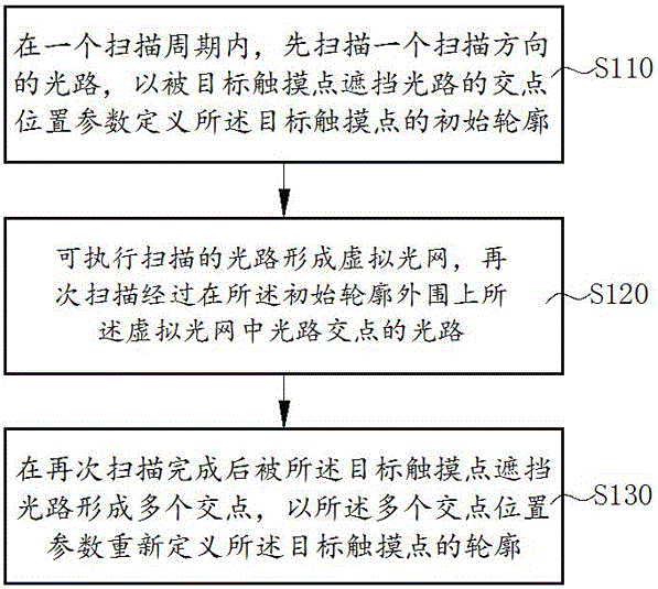
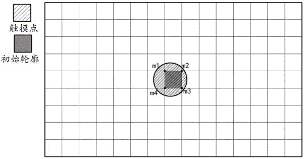
The embodiment of the invention provides a location method for touch point on infrared touch-control device and device and terminal equipment, the invention provides an identification method, wherein a light path is scanned from a scanning direction, and an initial profile of the aim touch point is defined for intersection point location parameter sheltered the light path from the aim touch point; executable scanned light path is formed with a virtual optical network, the light path of intersection point in the virtual optical network is second scanned from the periphery of the initial profile; the aim touch point sheltered the light path is formed a plurality of the intersection point, the location parameter of a plurality of the intersection point is defined with the profile of the aim touch point. According to the initial profile, part scanned light path is selected in the all scanned light path, and the initial profile is scanned again, number of the executive scanned light path is reduced when the infrared touch-control device is identified for the touch point.

Description

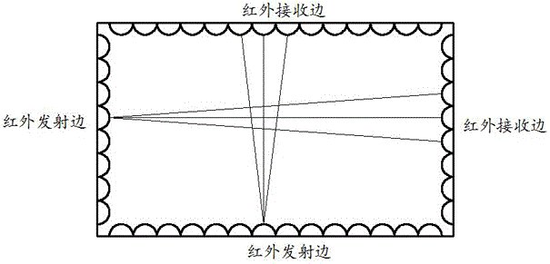
technical field [0001] The present invention relates to the field of infrared touch control, in particular to a method and device for locating a touch point on an infrared touch device and a terminal device. Background technique [0002] Two adjacent sides of the infrared touch device are provided with a plurality of infrared emitting tubes, and a plurality of infrared receiving tubes are arranged on the other two adjacent sides, corresponding to the infrared emitting tubes arranged on the opposite side, and the infrared emitting tubes emit infrared rays outward. The corresponding infrared receiving tube receives the infrared light, and the structure diagram of the infrared touch device is as follows: figure 1 shown. Usually one infrared emitting tube corresponds to multiple infrared receiving tubes. When one emitting tube emits infrared light, multiple receiving tubes on the opposite side receive the transmitted infrared light at the same time. The line taken is the scann...

Claims


Application Information

Patent Timeline
Patent Type & Authority Applications(China)
IPC IPC(8): G06F3/042
CPCG06F3/0421
Inventor 王武军马亮曹建伟
Owner HISENSE VISUAL TECH CO LTD
Learn More