Ultrasonic apparatus and control method therefor

a technology of ultrasonic apparatus and control method, applied in the field of ultrasonic, can solve the problems of inability to achieve real-time processing of all frames, inability to apply such a conventional technique to dynamic image processing, and inability to reduce the frame rate of dynamic image, etc., to achieve accurate contours and boundaries

Inactive Publication Date: 2011-04-07
CANON KK
View PDF4 Cites 18 Cited by
  • Summary
  • Abstract
  • Description
  • Claims
  • Application Information

AI Technical Summary

Benefits of technology

[0011]According to the present invention, an accurate contour (boundary) can be extracted in real time from an ultrasonic wave dynamic image in motion. Accordingly for example, it is possible to dynamically extract and observe a boundary of a diagnostic region while moving an ultrasonic probe.

Problems solved by technology

However, the conventional boundary extraction technique involves a problem that it is difficult to achieve such real-time processing.
In such a technique, the amount of calculation becomes huge (though it depends on the processing power of the apparatus), processing of all the frames in real time is not practical.
Therefore, to apply such a conventional technique to dynamic image processing could not help reducing the frame rate of the dynamic image.

Method used


Image

  • Ultrasonic apparatus and control method therefor
  • Ultrasonic apparatus and control method therefor
  • Ultrasonic apparatus and control method therefor

Examples


first embodiment

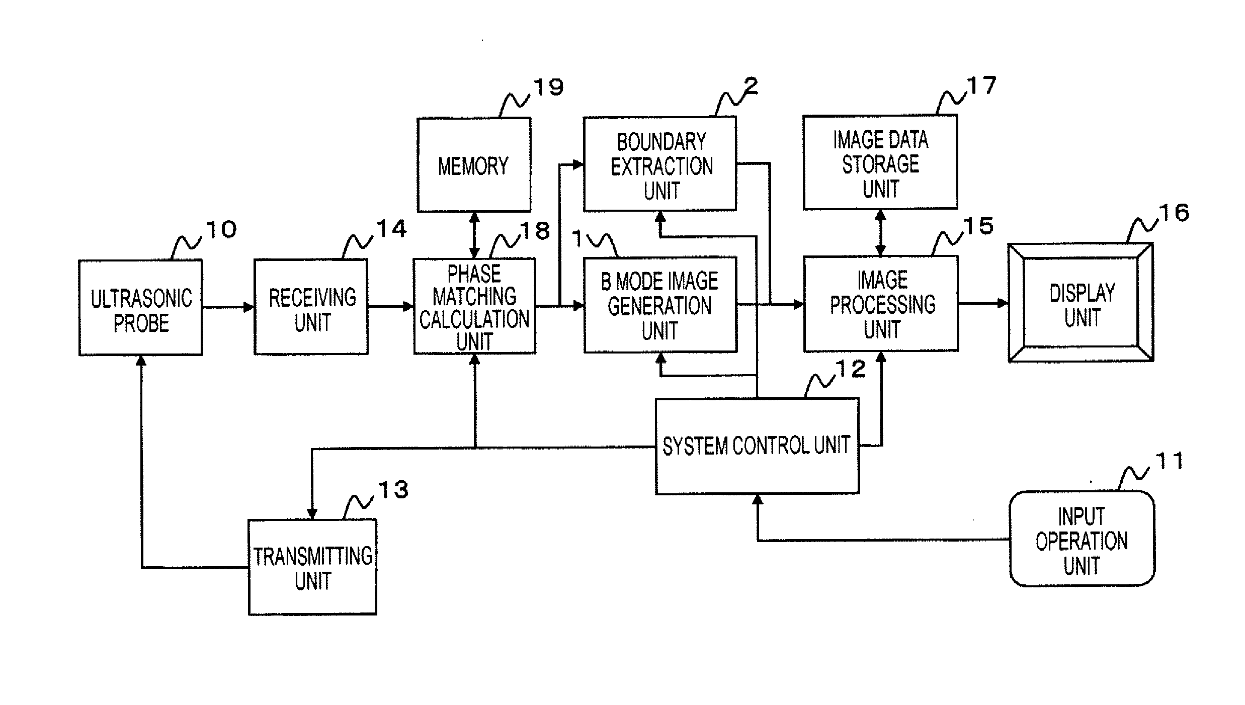
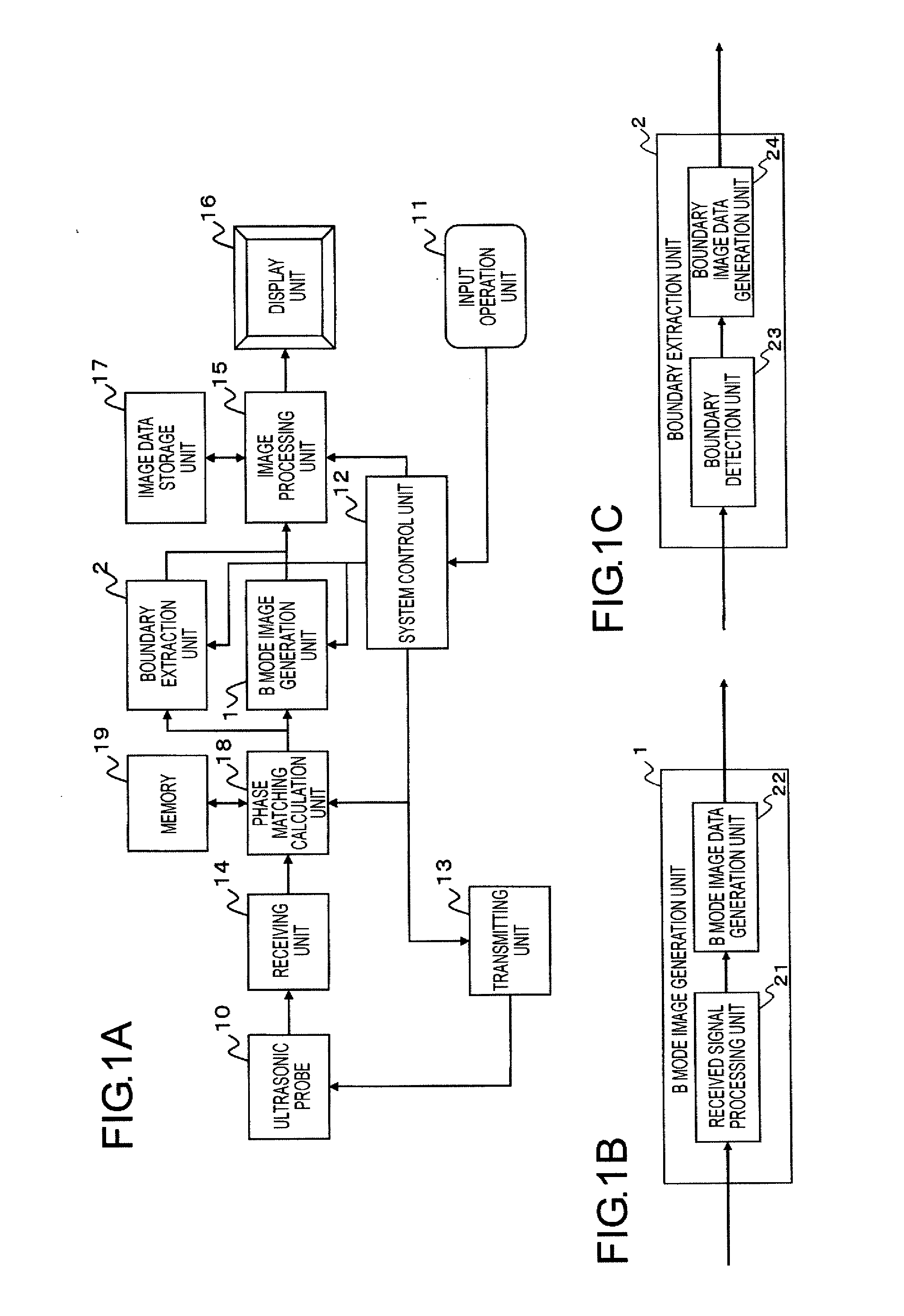
[0021]FIG. 1A is a block diagram illustrating the construction of an ultrasonic diagnostic apparatus according to a first embodiment of the present invention. The ultrasonic diagnostic apparatus according to this embodiment is provided with a function (boundary extraction unit 2) to extract a boundary between different tissues (between media) in addition to a B mode image generation function (B mode image generation unit 1) which is possessed by a general ultrasonic diagnostic apparatus.

[0022]As illustrated in FIG. 1A, the ultrasonic diagnostic apparatus according to this embodiment includes an ultrasonic probe 10, an input operation unit 11, a system control unit 12, a transmitting unit 13, a receiving unit 14, an image processing unit 15, a display unit 16, and an image data storage unit 17. In addition, the ultrasonic diagnostic apparatus is further provided with a phase matching calculation unit 18 and a memory 19.

[0023](Ultrasonic Probe)

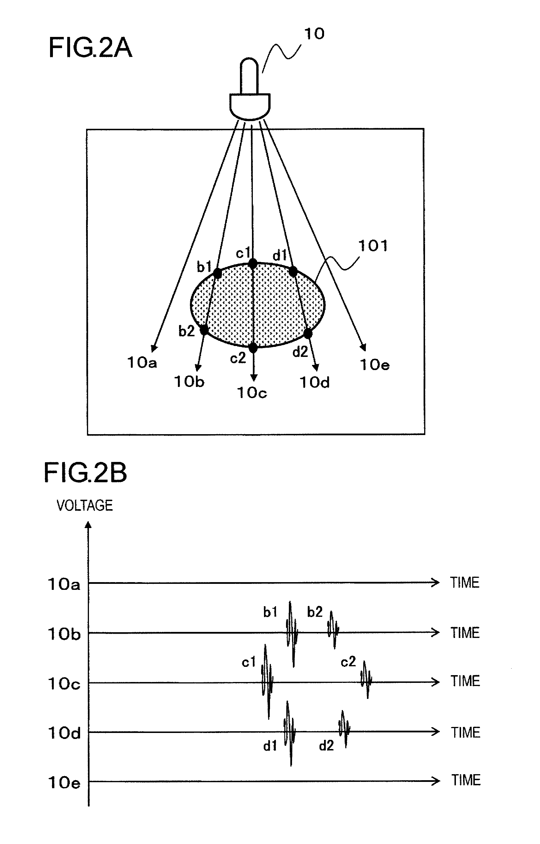
[0024]The ultrasonic probe 10 is used so ...

second embodiment

[0061]Next, reference will be made to an ultrasonic diagnostic apparatus according to a second embodiment of the present invention. The ultrasonic diagnostic apparatus of this second embodiment is different from that of the first embodiment in that it has a sound speed setting function to set the value of sound speed for each region delimited by a boundary. The other construction of this second embodiment is similar to that of the first embodiment, and hence in the following, those which are different from the first embodiment will be mainly described.

[0062]In a conventional ultrasonic diagnostic apparatus, a delay time in the electronic focus is calculated on the assumption that the speed of sound in a living body is a specific value (in general, 1,530 m / sec or 1,540 m / sec as specified in JIS). However, in actuality, the speed of sound is different according to the kind of tissues (media). In general, the speed of sound is about 3,000 m / sec in bone, about 1,590 m / sec in muscle, and...


PUM


Abstract

An ultrasonic diagnostic apparatus is provided with a boundary extraction unit (2) that extracts boundaries between media appearing in an ultrasonic image based on the intensity of each of received signals. A boundary extraction unit performs boundary extraction processing on each of individual time series ultrasonic images sequentially generated while operating an ultrasonic probe to move, sets a target region (margin region) matched to a movement operation of the ultrasonic probe in an ultrasonic image being processed from a boundary extracted in an ultrasonic image preceding the ultrasonic image being processed, and performs processing of extracting a boundary in the ultrasonic image being processed by using received signals corresponding to the reflection waves reflected at an inner side of the target region thus set.

Description

TECHNICAL FIELD[0001]The present invention relates to a technique for imaging the interior of an object to be inspected by using ultrasonic waves.BACKGROUND ART[0002]As an ultrasonic apparatus for imaging the interior of an object (specimen) to be inspected by using ultrasonic waves, there has been known an ultrasonic diagnostic apparatus for use in medical diagnosis, for example. In the ultrasonic apparatus, an ultrasonic probe is used which includes a plurality of ultrasonic transducers having the function of transmitting and receiving ultrasonic waves. When an ultrasonic beam formed in combination of a plurality of ultrasonic waves is transmitted from the ultrasonic probe to the specimen, the ultrasonic beam is reflected in a region of different acoustic impedance (i.e., a boundary of a tissue) in the interior of the specimen. The appearance in the interior of the specimen can be reproduced on a screen by receiving an ultrasonic wave echo generated in this manner and constructing...

Claims


Application Information

Patent Timeline
Patent Type & Authority Applications(United States)
IPC IPC(8): A61B8/14
CPCA61B8/0833A61B8/0858A61B8/483G06T2207/30096G01S7/52063G06T7/0083G06T2207/10132G01S7/52046G06T7/12
Inventor TATEYAMA, JIRO
Owner CANON KK
Why Eureka
Try Eureka