Apparatus for disperser plate and method to refine paper

a technology of disperser plate and disperser plate, which is applied in the field of disperser plate, can solve the problems of reducing the value of reconstituted paper, residual ink and toner particles can appear as blemishes in reconstituted paper, and sticking to the paper-making machine,

Active Publication Date: 2014-07-17
ANDRITZ INC
View PDF4 Cites 17 Cited by
  • Summary
  • Abstract
  • Description
  • Claims
  • Application Information

AI Technical Summary

Benefits of technology

The patent describes a new type of plate used in paper recycling and other applications. The plate can be used for both dispersing inks and toners and developing fibers. The plate has bars with flat surfaces and a narrow gap between them, which allows for precise positioning between the plate and the machine. This new plate design helps improve the performance of both dispersing and refining in the same machine.

Problems solved by technology

If stickies are not properly removed, the stickies can adhere to the paper-making machine and create holes or weak spots in the reconstituted paper formed by the recovered paper and packaging material.
Further, residual ink and toner particles can appear as blemishes in the reconstituted paper.
Blemishes generally reduce the value of reconstituted paper.
However, bar and groove patterns of refiner plates mounted on the discs of a conventional mechanical refiner are not well-suited to processing recovered paper and packaging material, in part, because the presence of ink and stickies.
To remove stickies, dispersers require a thick fiber pad to form between the plates; the required thick fiber pad is not achieved with conventional bar and groove patterns.
The bars of a conventional mechanical refiner plate are not well-suited to creating the thick fiber pad needed for optimal dispersion action.
Furthermore, the frequency at which bars cross in a typical or conventional mechanical refiner would be too high to adequately break up the stickies.

Method used


Image

  • Apparatus for disperser plate and method to refine paper
  • Apparatus for disperser plate and method to refine paper
  • Apparatus for disperser plate and method to refine paper

Examples


Embodiment Construction

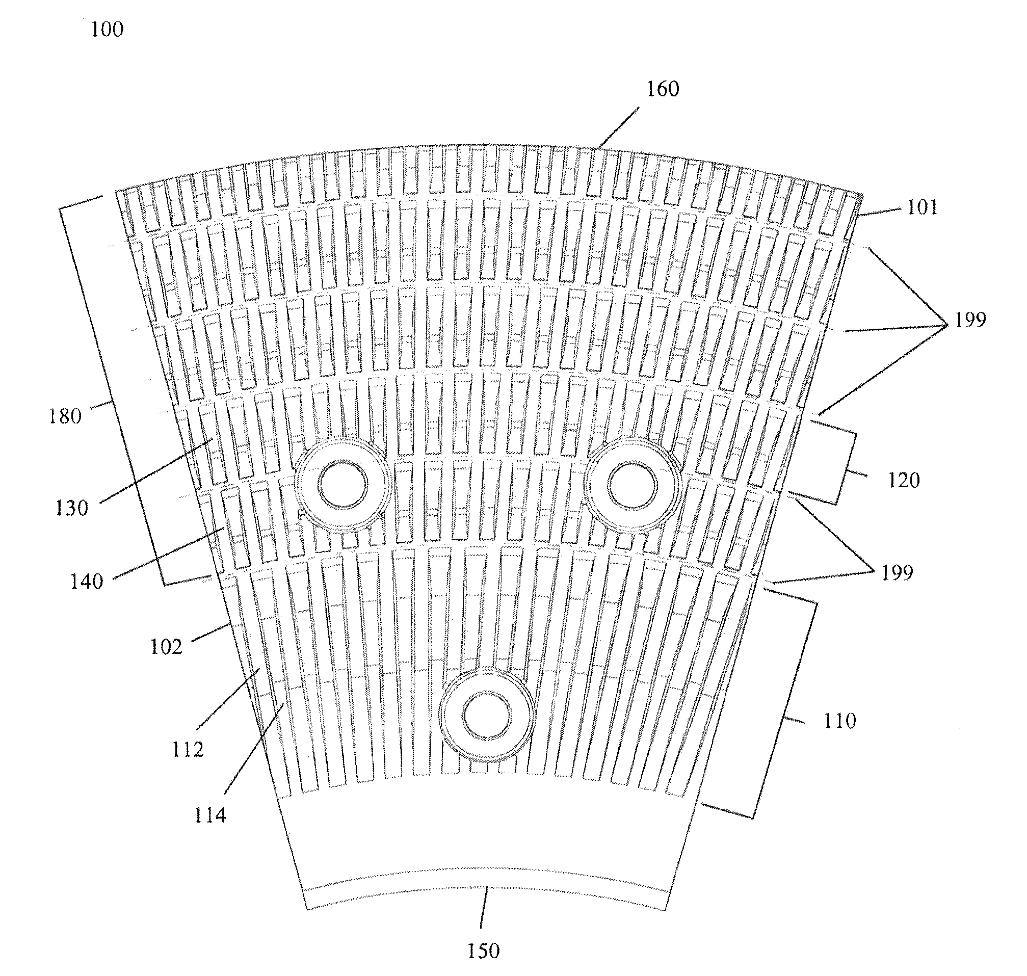
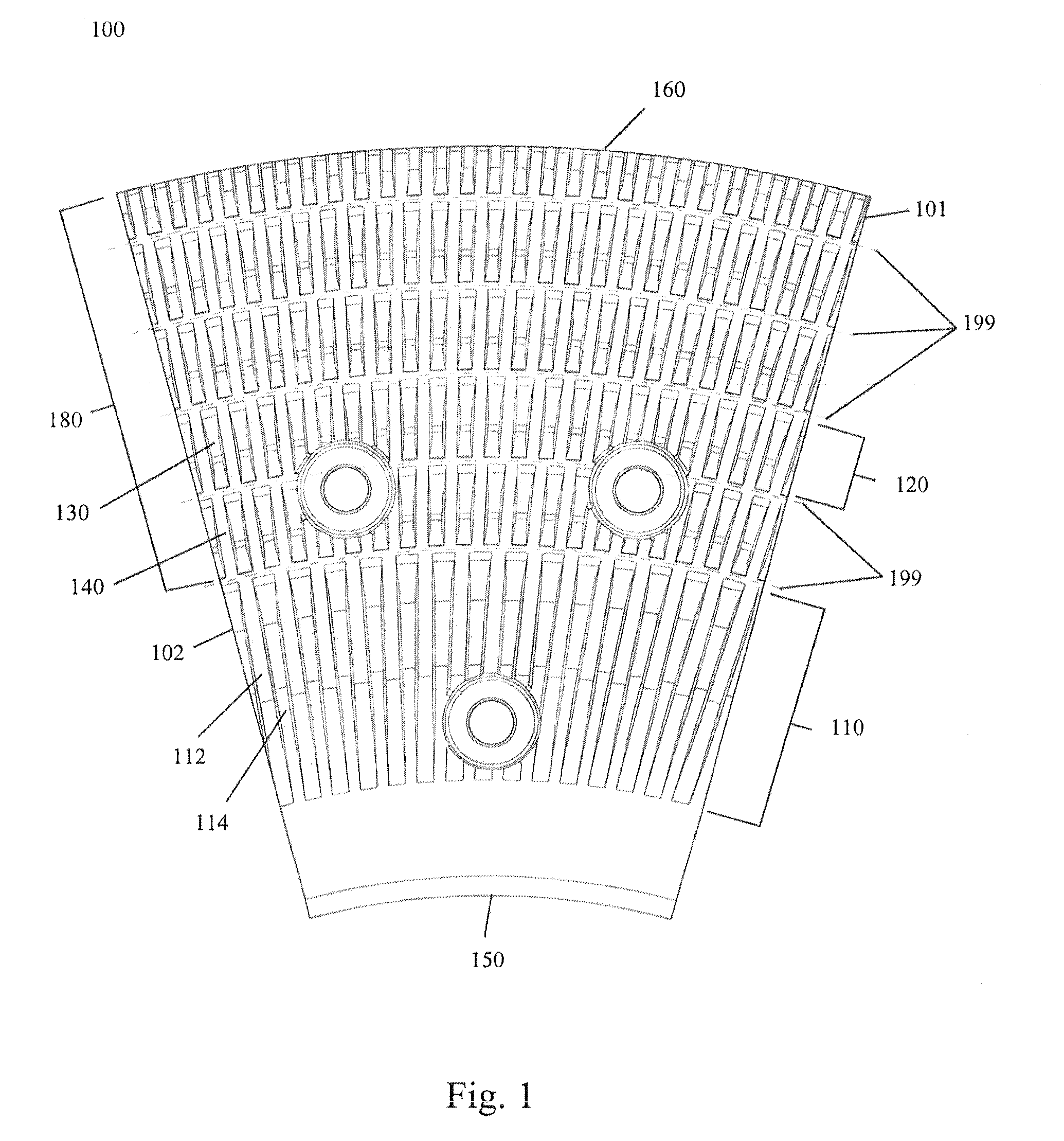
[0040]The need to combine dispersing and refining functions to recover and reuse paper and other packaging materials presents unique requirements for the discs and cones for dispersers. New plates or plate segments for mounting on stator and rotor discs and cones have been conceived and developed to overcome the disadvantages of using either a conventional refining plate mounted on a refining disc or cone, or a conventional dispersing plate mounted on a conventional dispersing disc or cone to obtain the needed separation of ink and other contaminants and provide desired refining of the recycled material.

[0041]FIG. 1 shows a segment of a stator fusion plate segment 100 (a fusion plate segment for mounting on a stator disc) useful for performing both dispersing and refining actions. The stator fusion plate segment 100 is has a feeder zone 110, beginning at the inner portion or inner periphery 150 of the stator fusion plate segment 100, and a processing zone 180 extending radially outw...


PUM

PropertyMeasurementUnit
widthaaaaaaaaaa
angleaaaaaaaaaa
angleaaaaaaaaaa

Abstract

An assembly of opposing discs or cones for a disperser where each disc or cone has mounted to it a plate or an array of plate segments with a front surface on each plate or array of plate segments and each surface has a series of bars, grooves and dams. The bars are in rows, with the rows separated by annular dams at substantially fixed radial locations, and the grooves are adjacent the bars in the rows so that the grooves form a serpentine passage extending radially between the opposing plates or array of plate segments on the opposing discs or cones. The opposing plate or array of plate segments are arranged such that the annular dams on one plate or array of plate segments face roughly the middle of the row of bars on the opposing plate or array of plate segments.

Description

CROSS-REFERENCE TO PRIOR APPLICATION[0001]This application claims the benefit of priority to U.S. App. No. 61 / 736,876 filed on Dec. 13, 2012, the entire contents of which are incorporated herein by reference.TECHNICAL FIELD[0002]This disclosure relates to disperser machines for converting paper to pulp and particularly to plates for disperser machines.BACKGROUND OF THE INVENTION[0003]It is desirable to recycle paper and packaging materials to reduce waste and reuse valuable natural resources. Recovered paper and packaging materials are subjected to several processes to remove ink, toner, and other contaminants such as glue and plastics that are commonly found on used paper and packing materials. The glue, plastics, and other similar contaminants are generally referred to as “stickies” by those skilled in the art. It is desirable for the ink, toner, and stickies to be removed before the recovered paper and packing materials are introduced into, for example, a paper-making machine.[00...

Claims


Application Information

Patent Timeline
Patent Type & Authority Applications(United States)
IPC IPC(8): D21B1/08
CPCD21B1/08D21D1/008B02C7/12D21D1/306D21D1/22D21D1/26D21D1/30D21F9/00
Inventor GINGRAS, LUC
Owner ANDRITZ INC
Why Eureka
Try Eureka