Key switch having good balance

A balanced, key-pressing technology, applied in electrical switches, electrical components, circuits, etc., can solve problems such as unsmooth use, affecting normal use, and pressing feeling, so as to improve pressing balance and pressing stability, and enhance pressing. Feel, with the effect of lengthening

Inactive Publication Date: 2017-05-31
DONGGUAN CITY KAIHUA ELECTRONICS
View PDF6 Cites 1 Cited by
  • Summary
  • Abstract
  • Description
  • Claims
  • Application Information

AI Technical Summary

Problems solved by technology

Existing thin key switches that use metal sheets as moving contacts cannot have the same pressing feel as large key switches due to the limitation of the internal space of the switch.
At the same time, due to the unreasonable design of the internal structure, the pressing stability is poor, resulting in unsmooth use and affecting normal use; and often there will be a feeling of jamming when pressing, which affects the pressing feel

Method used


Image

  • Key switch having good balance
  • Key switch having good balance
  • Key switch having good balance

Examples


Embodiment 1

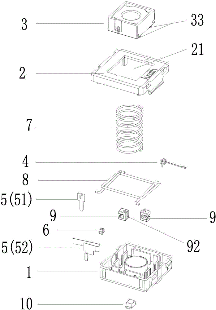
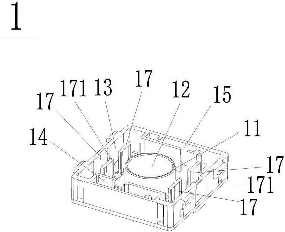
[0037] Please refer to Figure 1 to Figure 11 , the present embodiment provides a key switch with good balance, including a base 1 and a cover 2 covering the base 1, an opening 21 is opened on the cover 2, and the base 1 is also provided with The guide core 3, the torsion spring 4, the conduction assembly 5 and the guide core slider 6, wherein a guide post 11 protrudes upward at the center of the upper end of the base 1, and a guide post 11 is provided downward at the center of the guide post 11. Holes 12, one end of the base 1 is provided with a conduction assembly slot 14 for the insertion of the conduction assembly 5, and the other end is provided with a torsion spring slot 15 for the insertion of the torsion spring 4, on the upper end of the base 1 and located in the guide Two baffles 17 are respectively arranged on opposite sides of the column 11, and there is a gap 171 between the two baffles 17, so that the base 1 forms an annular accommodating groove around the baffle ...

Embodiment 2

[0044] Such as Figure 12 As shown, the main difference between this embodiment and Embodiment 1 is that the side of the positioning slider 9' in this embodiment is also provided with an arc-shaped limiter for the first balance bar 81 and the second balance bar 82 to snap into. The positioning slot 91', the limiting slot 91' has an opening 911', and the upper and lower parts of the opening 911' are respectively bent inward to form a protrusion 912'. However, the end surface of the protrusion 912 ′ in this embodiment is not provided with an angle, and the thickness of the positioning slider 9 ′ in this embodiment is thinner than that of the positioning slider 9 in the first embodiment.

Embodiment 3

[0046] Such as Figure 7 , Figure 10 , Figure 13 , Figure 14 and Figure 15 As shown, the main difference between the present embodiment and the first embodiment is that a groove is opened on the lower end surface of the guide core 3 , so that a plurality of guide core lobes 33 are formed on the lower end surface of the guide core 3 . At the same time, there are two ways to provide space for the guide core lobe 33, one of which is: on the base 1 and outside the guide post 11, there are several space for the guide core lobe 33 to extend into. groove 16, and the depth of the relief groove 16 is just equal to the height of the guide core lobe 33; another way is: on the base 1 and outside the guide post 11, there is a hole for the guide core lobe 33 to pass through A number of give way holes 16'.

[0047] In this embodiment, the number of the relief groove 16 and the relief hole 16' is the same as the number of guide core lobes 33. In this embodiment, the number of guide c...


PUM


Abstract

The invention discloses a key switch having good balance. The key switch having the good balance comprises a base seat and a cap covering the base seat, and further comprises a guide core, a torsional spring, a conducting component and a guide core sliding block, which are respectively arranged on the base seat, wherein a guiding pillar is arranged at the central position of the upper end of the base seat in upward protruded mode, a guiding hole is formed downwards in the center of the guiding pillar, two baffles are respectively arranged at the upper end of the base seat and located on two opposite side edges of the guiding pillar so as to form an annular containing groove which surrounds the baffles and the guiding pillar, an annular insertion groove is formed in the lower end of the guide core, an insertion pillar is arranged in the middle of the annular insertion groove in downward protruded mode, the insertion pillar is inserted into the guiding hole in the base seat so as to insert the guiding pillar into the annular insertion groove, springs sleeve the outer sides of the guiding pillar and the insertion pillar, a balancing pole component mainly formed by intersecting a first balancing pole with a second balancing pole is arranged in the annular containing groove, and positions of two opposite intersections of the first balancing pole and the second balancing pole are respectively limited by positioning sliding blocks. The key switch having the good balance significantly improves pressing balance and pressing stability.

Description

technical field [0001] The invention relates to a key switch, in particular to a key switch with good balance. Background technique [0002] Many operations of electronic devices require the use of key switches as input means. The quality of the key switch determines the experience of the input device, which requires the key switch to have a good feel and sound. Existing thin key switches that use metal sheets as moving contacts cannot have the same pressing feel as large key switches due to the limitation of the internal space of the switch. At the same time, due to the unreasonable design of the internal structure, the pressing stability is poor, resulting in unsmooth use and affecting normal use; and often there will be a sticky feeling when pressing, which affects the pressing feel. Contents of the invention [0003] In view of the above deficiencies, the object of the present invention is to provide a well-balanced key switch, which has a reasonable structural design...

Claims


Application Information

Patent Timeline
Patent Type & Authority Applications(China)
IPC IPC(8): H01H13/14H01H13/10
CPCH01H13/10H01H13/14H01H3/125H01H13/023H01H2013/525H01H13/52
Inventor 吴福喜
Owner DONGGUAN CITY KAIHUA ELECTRONICS
Why Eureka
Try Eureka