
Valved conduit

A pipeline, valved technology, applied in heart valve, medical science, prosthesis, etc., can solve problems such as reduced durability

Active Publication Date: 2017-05-31
WL GORE & ASSOC INC
View PDF12 Cites 10 Cited by
  • Summary
  • Abstract
  • Description
  • Claims
  • Application Information

AI Technical Summary

Problems solved by technology

In addition, all perforations and resulting sutures threaded therethrough are exposed to blood flow and are precisely positioned at the leaflet's deflection line at the leaflet base, which can lead to reduced durability

Method used


Image

  • Valved conduit
  • Valved conduit
  • Valved conduit

Examples


Embodiment Construction

[0035] Those skilled in the art will readily appreciate that various aspects of the present disclosure may be implemented by numerous methods and apparatuses configured to perform the intended functions. In other words, other methods and devices may be incorporated herein to perform the intended functions. It should also be noted that the drawings referred to herein are not necessarily drawn to scale, but may be exaggerated to illustrate various aspects of the present disclosure and in this regard, the drawings should not be considered limiting.

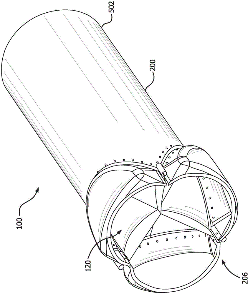
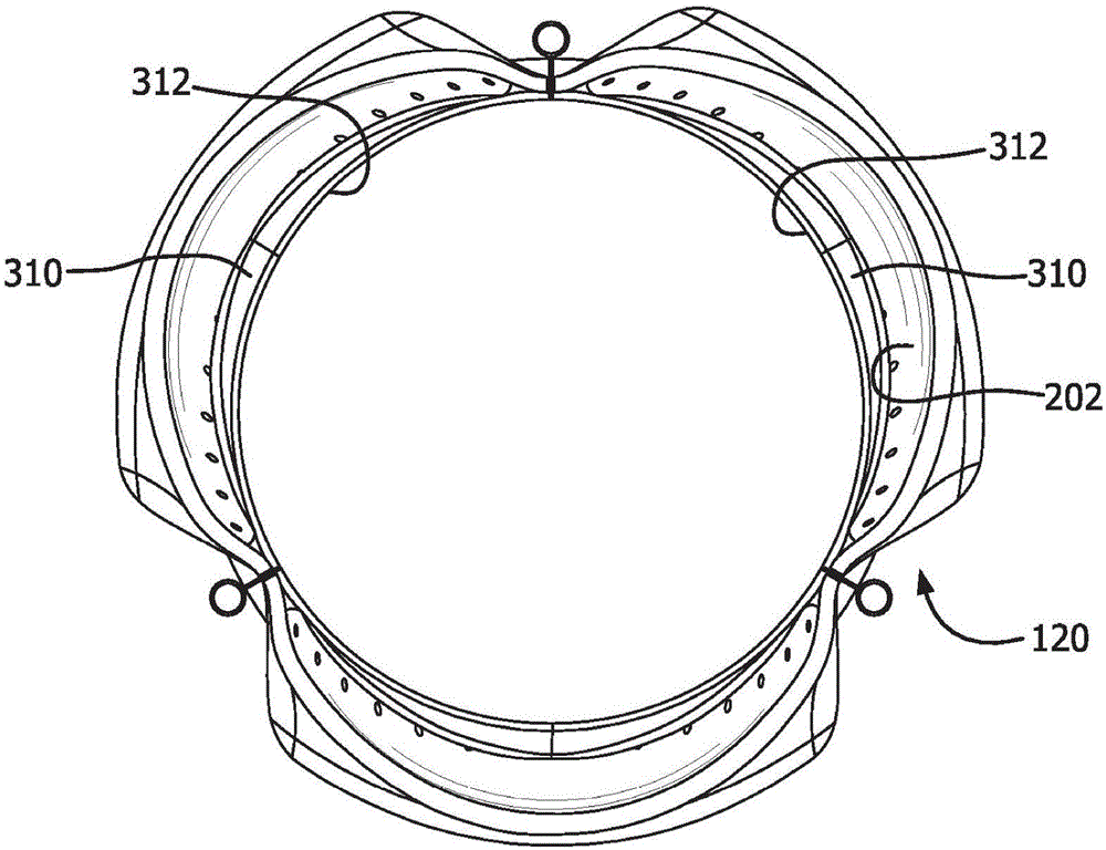
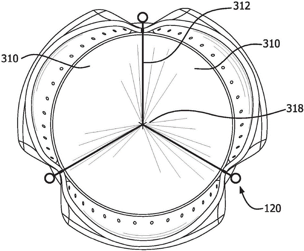
[0036] Although the embodiments herein may be described in conjunction with various principles and perspectives, the described embodiments should not be bound by theory. For example, embodiments are described herein in connection with a prosthetic valved conduit. However, embodiments within the scope of the present disclosure may be applied to any valved conduit, valve structure or mechanism having similar structure and / or function....


PUM


Abstract

The invention relates to a valved conduit. The valved conduit includes a leaflet construct coupled between two portions of a conduit. Each leaflet has a free edge and a leaflet attachment edge. The leaflet attachment edge is disposed between a first conduit distal end and a second conduit proximal end that are coaxial therebetween defining a junction.

Description

technical field [0001] The present disclosure relates generally to prosthetic valves, and more particularly to conduits having valve structures therein. Background technique [0002] Various manufacturing techniques have been used to couple the leaflets to the interior of the duct, including suturing the individual leaflets to the inner surface of the duct. In many cases, the resulting leaflets are supported on the inner surface of the conduit and define a valve having a mounting edge where the leaflet is coupled to the inner surface of the conduit and a free edge that allows movement of the valve. The valve moves under the influence of fluid pressure. In operation, the leaflets open to allow flow through the conduit when upstream fluid pressure exceeds downstream fluid pressure, and close and prevent flow through the conduit when downstream fluid pressure exceeds upstream fluid pressure. [0003] The process of fitting the leaflets to the inner surface of the duct is tedi...

Claims


Application Information

Patent Timeline
IPC IPC(8): A61F2/24
CPCA61F2/2415A61F2/2418A61F2220/0075A61F2220/005A61F2220/0058A61F2230/008A61F2230/0069A61F2250/0098A61F2/2412A61F2/2409
Inventor J·R·阿姆斯特朗N·L·贝内特K·W·科拉维托E·W·费尔德
Owner WL GORE & ASSOC INC
Learn More