Valved catheter

a catheter and valve technology, applied in the field of valved catheters, can solve the problems of increasing the burden on the medical practitioner and the patient, the operation pertaining to the placement of the catheter in the patient's body is more troublesome, and the blood can infiltrate into the bloodstream, so as to achieve the effect of convenient opening, convenient opening and convenient opening

Active Publication Date: 2011-03-03
MOZARC MEDICAL US LLC
View PDF100 Cites 6 Cited by
  • Summary
  • Abstract
  • Description
  • Claims
  • Application Information

AI Technical Summary

Benefits of technology

[0007]With the foregoing conditions in mind, it is an object of the present disclosure to provide a valved catheter that includes a slit that opens readily in both directions when either a fluid is caused to flow from the interior to the exterior thereof or when a fluid is caused to flow from the exterior to the interior thereof, and that prevents inadvertent closure thereof from the opened state.

Problems solved by technology

However, when catheters with an open distal end are employed, blood is able to infiltrate into the catheter where it coagulates and causes the blockage thereof.
While catheter blockage by blood is commonly prevented by filling the lumen of the catheter with a heparin-added physiological saline solution or the like, this renders the operation pertaining to the placement of the catheter in the body of the patient more troublesome and, moreover, increases the burden on the medical practitioner and the patient.
For this reason, the slit is less readily able to be opened from the closed state at low fluid pressure due to the pressure contact between these opposing surfaces, and is less readily able to be closed from the opened state.

Method used


Image

  • Valved catheter
  • Valved catheter
  • Valved catheter

Examples


first embodiment

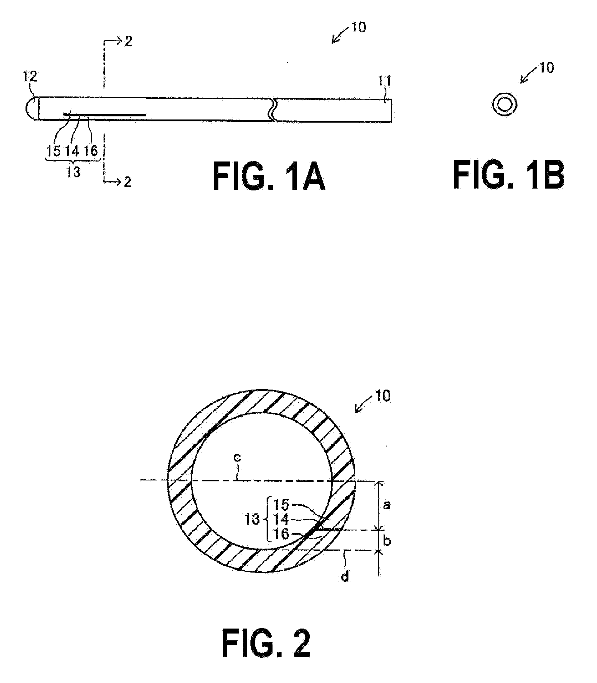
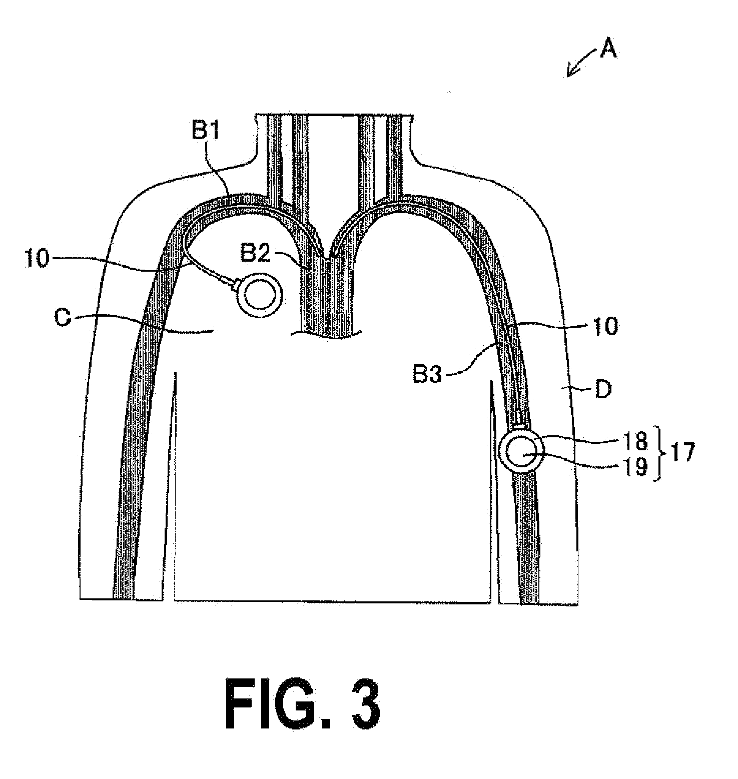
[0033]the valved catheter pertaining to the present disclosure will be hereinafter described in detail with reference to the drawings. FIGS. 1A-1B and FIG. 2 show a valved catheter 10 of this embodiment. The valved catheter 10, which is used for delivering a medical fluid such as an anticancer agent or nutrients into a vein (reference characters B1 to B3 and so on as shown in FIG. 3) of a patient A, is placed in the patient A by the connection of a port 17 to a proximal end portion 11 thereof. The valved catheter 10, which is constituted by an elongate, circular tube-shaped body composed of a soft polyurethane resin, is resilient and flexible.

[0034]In addition, a dome-shaped wall portion 12 is formed in the distal end of the valved catheter 10, and the distal end of the valved catheter 10 is closed by this wall portion 12. The wall portion 12, which is composed of silicon or polyurethane that is softer than the main body of the valved catheter 10, is fastened to the main body of the...

second embodiment

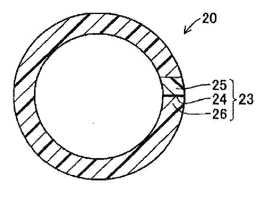
[0045]FIG. 4 and FIG. 5 show a valved catheter 20 pertaining to the present disclosure. Similarly to the valved catheter 10 described above, the valved catheter 20 has an open proximal end portion 21 and a dome-shaped wall portion 22 formed in its distal end. A valve 23 of this embodiment is constituted by a linear slit 24 provided to extend in the axial direction of the valved catheter 20, and by edge portions 25, 26 formed in the two sides of the slit 24 in the circumferential direction. The slit 24 is formed in such a way as to lie on an imaginary straight line (not shown in the drawing) passing through a center point in the cross-section of the valved catheter 20 shown in FIG. 5.

[0046]In addition, while the resin material from which the edge portion 25 is constituted is a polyurethane of the same type as the other sections from which the valved catheter 20 is constituted, this polyurethane is softer than the polyurethane from which the other sections are constituted, and the sec...

third embodiment

[0048]FIG. 6 and FIG. 7 show a valved catheter 30 pertaining to the present disclosure. Similarly to the valved catheter 10, the valved catheter 30 includes an open proximal end portion 31 and has a dome-shaped wall portion 32 formed in its distal end. A valve 33 thereof is constituted by a linear slit 34 provided to extend in the axial direction of the valved catheter 30, edge portions 35, 36 formed in the two sides of the slit 34 in the circumferential direction, and a contrast-imparted portion 37 formed in the interior of the edge portion 35. The slit 34 is formed in such a way as to lie on an imaginary straight line (not shown in the drawing) passing through a center point in the cross-section of the valved catheter 30 shown in FIG. 7.

[0049]In addition, the contrast-imparted portion 37, which is constituted by admixing a polyurethane resin with a contrast-imparting material composed of a barium or tungsten powder or the like of greater hardness than the polyurethane resin, is fo...


PUM


Abstract

A valved catheter is provided which includes a slit that opens readily in both directions either when a fluid is caused to flow from the interior to the exterior thereof or when a fluid is caused to flow from the exterior to the interior thereof, and that prevents inadvertent closure thereof from the opened state. The valve includes an openable slit that penetrates from the inner surface to the outer surface of a distal end section of a valved catheter with a closed distal end, and edge portions on the two sides of the slit are formed along the direction in which the valved catheter extends. The slit includes a linear shape in the cross-section of the distal end section of the valved catheter that extends in a position away from a center line “c” that passes through the center of the valved catheter in parallel with this center line “c” whereupon, either one of the edge portions deforms more readily than either one of the other edge portions.

Description

CROSS-REFERENCE TO RELATED APPLICATIONS[0001]This application claims priority under 35 U.S.C. §119 to Japanese Patent Application Serial No. 2009-199639, filed Aug. 31, 2009, the entire contents of which are incorporated by reference in their entirety.TECHNICAL FIELD[0002]The present disclosure relates to a valved catheter through which a fluid is able to pass from the interior to the exterior thereof, and from the exterior to the interior thereof, by way of a valve including a slit.DESCRIPTION OF RELATED ART[0003]The temporary and long-term delivery of medical fluids, including anti-cancer agents and nutrients, into the vein of a patient conventionally involves, for example, the placement of a catheter in the body of the patient. Stable injection of medical fluids employing such catheters necessitates the avoidance of catheter blockage while the medical fluid is being injected. However, when catheters with an open distal end are employed, blood is able to infiltrate into the cathet...

Claims


Application Information

Patent Timeline
Patent Type & Authority Applications(United States)
IPC IPC(8): A61M25/14
CPCA61M25/0075A61M2025/0076A61M39/22A61M25/01A61M2025/0078
Inventor ONUMA, TADATSUGUMAKINO, MASANORISONOYAMA, EMIYO
Owner MOZARC MEDICAL US LLC
Why Eureka
Try Eureka