Valved conduit and method for fabricating same

Inactive Publication Date: 2018-06-21
PECA LABS INC
View PDF0 Cites 5 Cited by
  • Summary
  • Abstract
  • Description
  • Claims
  • Application Information

AI Technical Summary

Benefits of technology

[0003]Various embodiments are directed to valves including: a conduit having an inner conduit surface and an outer conduit surface; and a valve structure comprising one or more leaflet, each leaflet having an outer sinus edge, an inner sinus edge, an open sinus edge and a fan, attached to the inner surface of the conduit at the outer sinus edge and inner sinus edge, wherein the open sinus edge is suspended below the inner surface of the conduit by a depth creating a sinus between the leaflet and the inner conduit surface. In some embodiments, each leaflet has a substantially triangular shape. In certain embodiments, each open sinus edge has a width that is less than the circumference of the conduit between fixture points of the leaflet to the conduit, and in particular embodiments, the outer sinus edge and the inner sinus edge may be attached to the conduit by a fluid impervious connection selected from the group consisting of suturing, welding, fusion, applying an adhesive, and combinations thereof. In various embodiments, the conduit and valve structure may each individually be composed of any biocompatible and hemocompatible polymer, and in such embodiments, the biocompatible and hemocompatible polymer may be a fluoropolymer such as, but not limited to, polytetrafluoroethylene, expanded polytetrafluoroethelyne, polyester, polyethylene terephthalate, polydimethylsiloxane, polyurethane, and combinations thereof. In particular embodiments, the biocompatible and hemocompatible polymer may be a polymer coated with a bioactive coating or surface-modified to include a bioactive material, and in such embodiments, the bioactive material may be an anti-coagulant coating, coumadin, heparin, a heparin derivative, a Factor Xa inhibitor, a direct thrombin inhibitor, hementin, sintered porous titanium microspheres, carbon coating, and combinations thereof. In some embodiments, each leaflet may have a ratio of width of the leaflet to a portion of a circumference of the conduit between fixing points of about 0.63 to about 1, and in certain embodiments, each leaflet may have a ratio of width of the leaflet to conduit diameter of about 0.9 to about 1.7. In some embodiments, the valve may further include a stent attached to an outer surface of the conduit.

Problems solved by technology

While this approach may offer some benefit over a valve-less conduit, homograft valves impart a number of other problems, including calcification, immune rejection, and occasional perforation of valve leaflets, among others. ePTFE valved conduits have been shown to greatly resist these issues, which has led to improved results compared to homograft for similar pediatric cardiac surgical procedures where larger-diameter valved conduits are used.

Method used


Image

  • Valved conduit and method for fabricating same
  • Valved conduit and method for fabricating same
  • Valved conduit and method for fabricating same

Examples


Embodiment Construction

[0018]Before the invention is described, it is to be understood that this invention is not limited to the particular systems, methodologies or protocols described, as these may vary. It is also to be understood that the terminology used herein is for the purpose of describing particular embodiments only, and is not intended to limit the scope of the present disclosure.

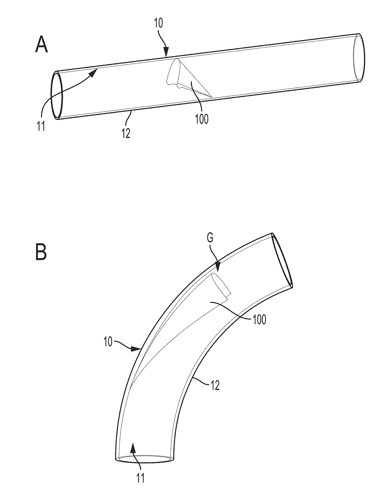
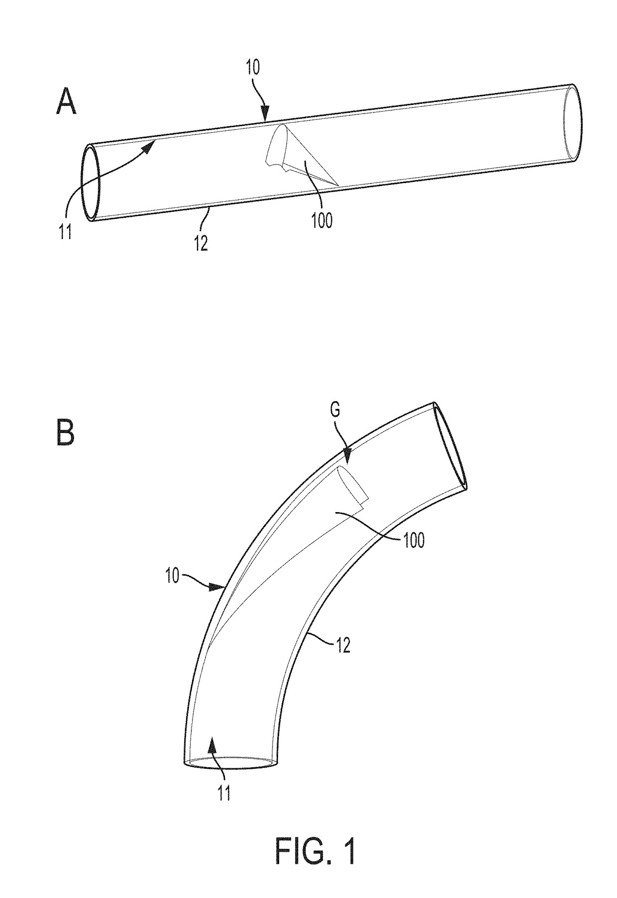
[0019]Various embodiments are directed to valved conduits having leaflets that do not contact the wall of the conduit in open position (FIG. 1B). As illustrated in FIGS. 1A and B, an example valved conduit encompassed by such embodiments may include a conduit 10 having an inner surface 11 and an outer surface 12. A valve 100 composed of one or more leaflets may be disposed within the conduit 10 and attached to the inner surface 11 of the conduit 10. In open position (FIG. 1B), a valve gap G separates the inner surface of the conduit 11 from the valve 100.

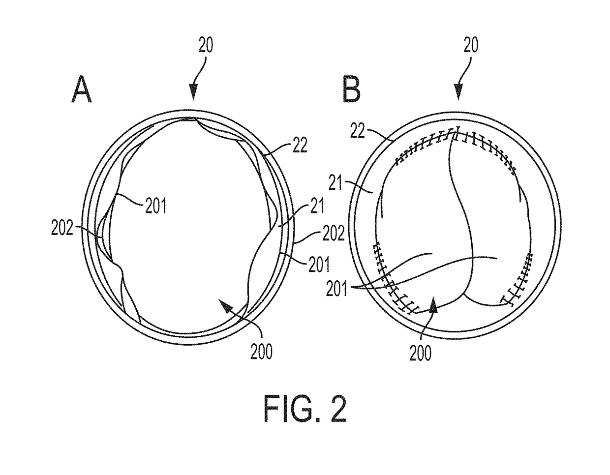
[0020]FIG. 2 is a cross-sectional view, showing a valve 200 in op...


PUM

PropertyMeasurementUnit
diameteraaaaaaaaaa
diameteraaaaaaaaaa
diameteraaaaaaaaaa

Abstract

Valved conduits having leaflet structures that do not contact an inner surface of a conduit in which they are formed are described herein.

Description

CROSS REFERENCE TO RELATED APPLICATION[0001]This application claims priority from U.S. Provisional No. 62 / 181,521, entitled “Valved Conduit and Method for Fabricating Same,” filed Jun. 18, 2015, the entirety of which is hereby incorporated by reference.BACKGROUND[0002]In attempts to provide valved conduits to patients undergoing, for example, the Norwood Procedure, some institutions have created hybrid valved conduits by attaching a homograft valve and to a synthetic conduit. While this approach may offer some benefit over a valve-less conduit, homograft valves impart a number of other problems, including calcification, immune rejection, and occasional perforation of valve leaflets, among others. ePTFE valved conduits have been shown to greatly resist these issues, which has led to improved results compared to homograft for similar pediatric cardiac surgical procedures where larger-diameter valved conduits are used. Following this precedent, a properly-functioning valved small-diame...

Claims


Application Information

Patent Timeline
Patent Type & Authority Applications(United States)
IPC IPC(8): A61F2/06A61F2/24
CPCA61F2/06A61F2/2415A61F2/2412A61F2220/005A61F2220/0058A61F2220/0075A61F2002/068A61F2240/001A61F2/2475A61L27/34A61L27/54A61L31/10A61L31/16A61L2300/42A61L2400/04A61L2430/20
Inventor BERNSTEIN, C. DOUGLASKALRA, ARUSH
Owner PECA LABS INC
Why Eureka
Try Eureka