
Pulling-out tool used for annular oil seal

An oil seal and ring technology, which is applied in the field of pulling out tooling for ring oil seals, can solve the problems of increased worker workload, heavy labor, and low efficiency, and achieve the effects of compact overall structure, improved applicability, and improved work efficiency

Inactive Publication Date: 2017-06-09
重庆健旺科技有限公司
View PDF0 Cites 3 Cited by
  • Summary
  • Abstract
  • Description
  • Claims
  • Application Information

AI Technical Summary

Problems solved by technology

[0003] However, during the long-term operation of the locomotive, in order to ensure the stable operation of the locomotive, it is necessary to detect and replace the LL-type oil seal in time and regularly. During the replacement process of the LL-type oil seal, the temporarily sealed oil seal unloading groove is usually opened. Then use tools such as pliers to pull the oil seal out of the bearing. Since the press-fitting of the LL-type oil seal is realized through a hydraulic press-fitting mold, the oil seal is tightly attached to the bearing. Manual operation requires a large amount of labor and increases the workload of the workers. , and the efficiency is low; another solution is to use large-scale precise automatic extraction equipment, but this method is expensive and unacceptable to ordinary enterprises

Method used


Image

  • Pulling-out tool used for annular oil seal
  • Pulling-out tool used for annular oil seal
  • Pulling-out tool used for annular oil seal

Examples


Embodiment 1

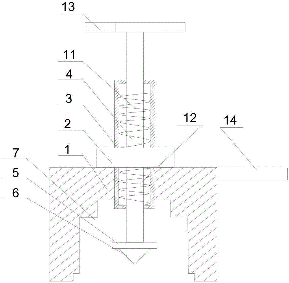
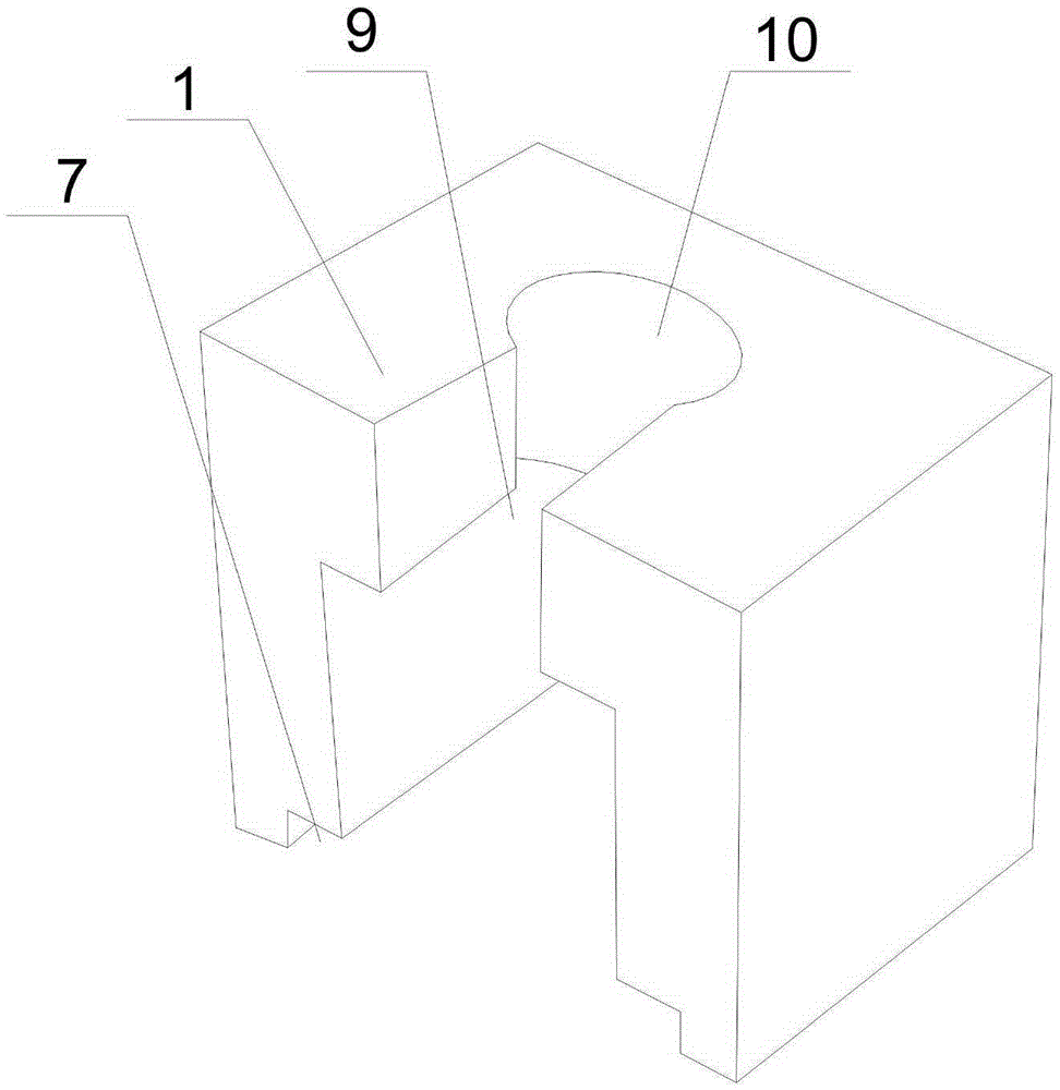
[0023] like Figure 1~Figure 3 As shown, this embodiment includes a support base 1 with a U-shaped groove at the bottom, a through hole 10 and an abdication hole 9 communicating with each other are opened at the upper end of the support base 1, and the extraction rod 4 passes through the through hole 10 and is placed in a U-shaped In the groove, a hollow and annular connecting cylinder 3 is set in the middle of the extracting rod 4, the connecting cylinder 3 is in contact with the inner wall of the through hole 10, and an external thread is also provided on the outer wall of the extracting rod 4, And the external thread is threadedly matched with the upper part of the inner wall of the connecting cylinder 3, and the end of the extraction rod 4 is rotated to be provided with a snap-in disc 5, the outer diameter of the snap-in disc 5 is larger than the outer diameter of the extraction rod 4; The nut 2, the screw nut 2 is threadedly matched with the connecting cylinder 3, the dia...


PUM


Abstract

The invention discloses a pulling-out tool used for an annular oil seal. The pulling-out tool comprises a supporting base which is provided with a U-shaped groove on the bottom, the upper end of the supporting base is provided with a hole and a backspace hole, a pulling-out rod passes through the hole and is arranged in the U-shaped groove, and the middle part of the pulling-out rod is sleeved with a connecting cylinder. The outer wall of the pulling-out rod is also provided with external threads, and the external threads are cooperated with the threads on the upper section of the inner wall of the connecting cylinder. The tail end of the pulling-out rod is rotatably provided with a clamping disk. The outer periphery of the clamping disk is symmetrically provided with two arc pits along the center of the disk. The outer diameter of the clamping disk is larger than the outer diameter of the pulling-out rod. A nut is cooperated with the connecting cylinder by threads. The diameter of the backspace hole is larger than the outer diameter of the connecting cylinder. The connecting cylinder slides along the inner wall of the backspace hole, until the connecting cylinder is completely moved out of the U-shaped groove. The pulling-out tool can realize detachable connection among components. Aimed at bearings in different types and models, the pulling-out rod can still accurately pass through a withdrawal groove and contact with the inner wall of an oil seal, so as to improve applicability of the pulling-out tool.

Description

technical field [0001] The invention relates to an LL type oil seal, in particular to a pull-out tool for an annular oil seal. Background technique [0002] The LL type oil seal is used for the sealing of the 353130B compact bearing, which can achieve the purpose of making the short shaft of the 353130B compact bearing less prone to bending and increasing the service life. Abrasive particles invade the bearing, which also makes the bearing have good sealing performance and improves the service life of the grease in the bearing. [0003] However, during the long-term operation of the locomotive, in order to ensure the stable operation of the locomotive, it is necessary to detect and replace the LL-type oil seal in time and regularly. During the replacement process of the LL-type oil seal, the temporarily sealed oil seal unloading groove is usually opened. Then use tools such as pliers to pull the oil seal out of the bearing. Since the press-fitting of the LL-type oil seal is...

Claims


Application Information

Patent Timeline
Patent Type & Authority Applications(China)
IPC IPC(8): B25B27/02
CPCB25B27/023B25B27/0035
Inventor 聂建仙
Owner 重庆健旺科技有限公司
Learn More