Fan device capable of improving the installation efficiency

An installation efficiency and fan technology, which is applied to the components of the pumping device for elastic fluids, mechanical equipment, machines/engines, etc. The effect of improving assembly efficiency

Inactive Publication Date: 2018-12-21
成都长江锅炉热能设备制造有限公司
View PDF0 Cites 0 Cited by
  • Summary
  • Abstract
  • Description
  • Claims
  • Application Information

AI Technical Summary

Problems solved by technology

[0005] The purpose of the present invention is to provide a fan device that improves the installation efficiency, and solves the problem that the existing partition is directly welded to the outer cylinder of the fixed fan, which is extremely inconvenient when maintaining the fan or cleaning the partition

Method used


Image

  • Fan device capable of improving the installation efficiency
  • Fan device capable of improving the installation efficiency
  • Fan device capable of improving the installation efficiency

Examples


Embodiment 1

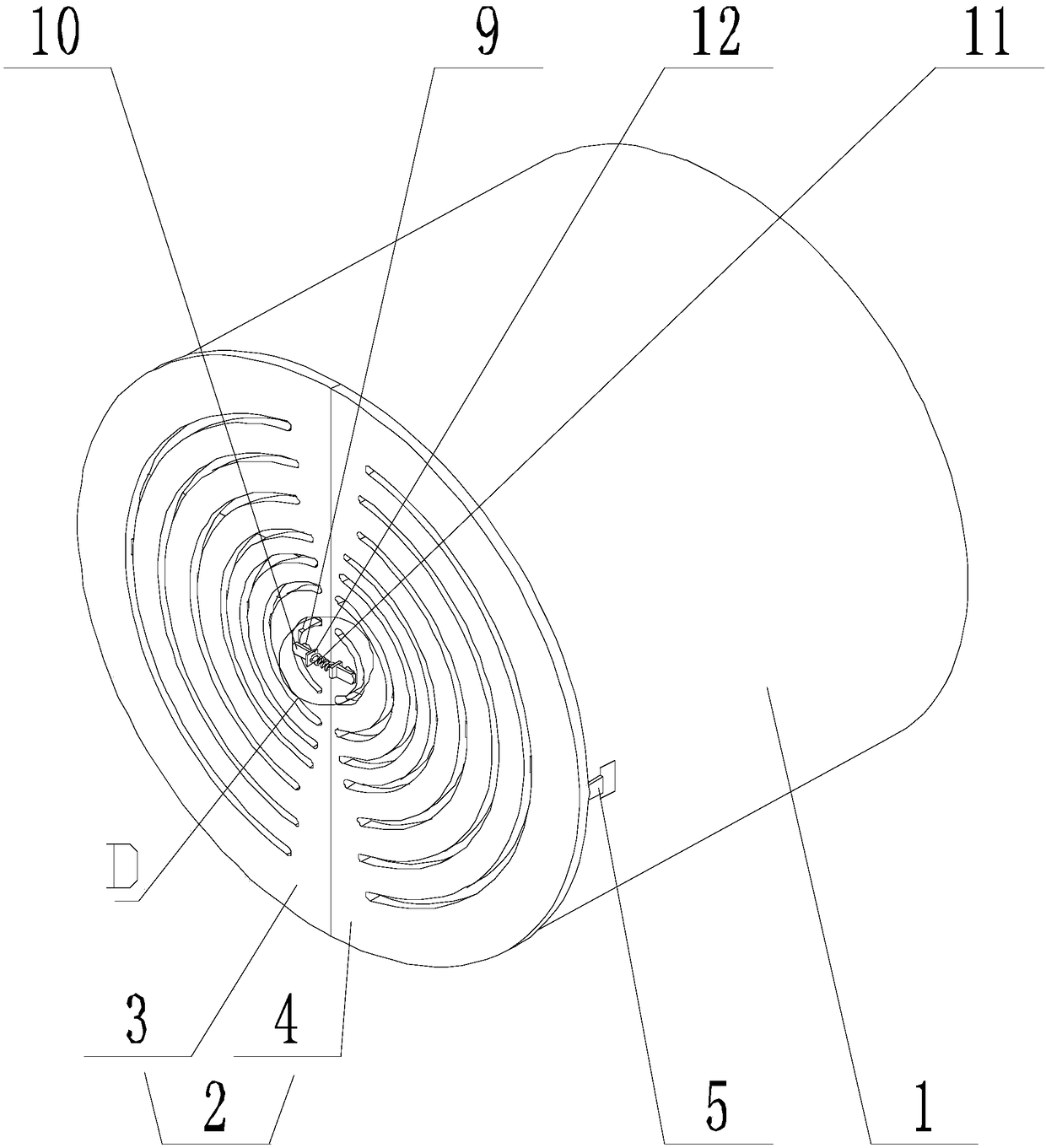
[0026] Such as Figure 1-Figure 5 As shown, the fan device for improving installation efficiency of the present invention includes a fan and a limiting component. The fan includes an outer cylinder 1, a fan assembly placed inside the outer cylinder 1, and a partition placed at one end of the outer cylinder 1 away from the air cooler. The net 2 is divided into a left net 3 and a right net 4 by a plane passing through the axis of the outer cylinder 1, and a slider 5 is provided on the left net 3 and the right net 4 on the side close to the outer cylinder 1. The other side of the left net 3 and the right net 4 are both provided with mounting holes 8;

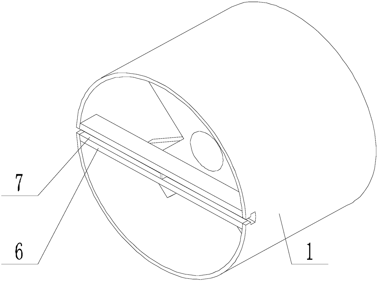
[0027] A mounting strip 6 is provided on the side of the central hole of the outer cylinder 1 close to the screen 2. Both ends of the mounting strip 6 are connected with the hole wall of the central hole. The side of the mounting strip 6 close to the screen 2 is provided Two sliding grooves 7, the extension axes of the sliding groove...

Embodiment 2

[0034] This embodiment is on the basis of Embodiment 1 to further illustrate the present invention.

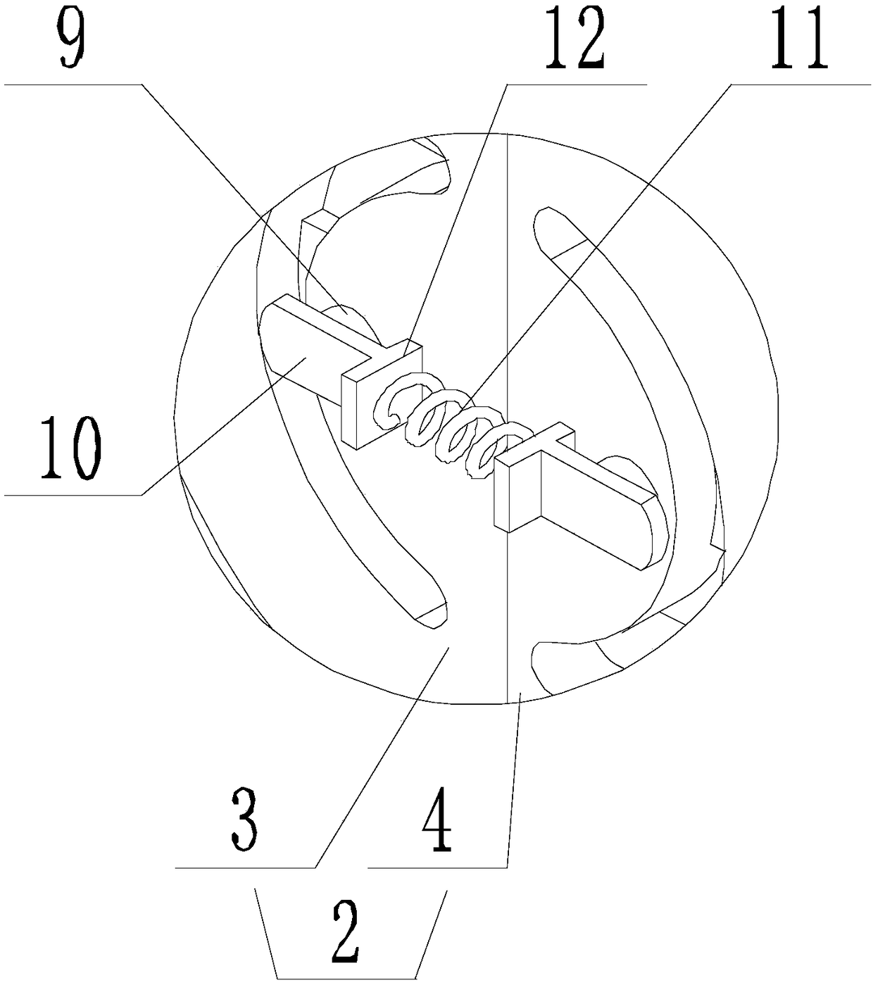
[0035] Such as Figure 1-Figure 5 As shown, in the fan device for improving installation efficiency of the present invention, a force plate 12 is provided between the connecting plate 10 and the spring 11, and the force plate 12 is perpendicular to the expansion and contraction direction of the spring 11, and the force plate 12 The two sides of are respectively connected to one end of the spring 11 and one end of the corresponding connecting plate 10;

[0036] The connecting plate 10 is parallel to the expansion and contraction direction of the spring 11 and perpendicular to the axis of the positioning shaft 9.

Embodiment 3

[0038] This embodiment is on the basis of Embodiment 1 to further illustrate the present invention.

[0039] Such as Figure 1-Figure 5 As shown, in the fan device with improved installation efficiency of the present invention, the opening size of the sliding groove 7 is smaller than the groove bottom dimension, and the cross-sectional size of the sliding block 5 matches the cross-sectional dimension of the sliding groove 7.

[0040] The opening size of the chute 7 is smaller than the size of the bottom of the groove, which restricts the movement of the left and right nets, so that it can only slide along the extending direction of the chute.


PUM


Abstract

The invention discloses a fan device capable of improving the installation efficiency. The fan device comprises a fan and a limiting assembly, the fan comprises an outer cylinder, a fan assembly and aseparation net, the separation net is divided into a left net and a right net by a plane, close to the outer cylinder, of the left net and the right net, sliding blocks are arranged on one side, close to the outer cylinder, of the left net and the right net, mounting holes are formed in the other side; a mounting strip is arranged on one side, close to the separation net, of the center hole of the outer cylinder, the two ends of the mounting strip are connected with a hole wall of the central hole, two sliding grooves are formed in one side, close to the separating net, of the mounting strip,the sliding blocks are respectively matched with one sliding grooves; the limiting assembly comprises a spring and positioning shafts, the number of the positioning shafts are two, the two positioning shafts are respectively connected with the springs through connecting plates, the positioning shafts are respectively inserted into mounting holes, the springs belongs to a stretching state. According to the fan device, the separation net and the outer cylinder are detachably connected, and maintenance and cleaning of the fan are facilitated.

Description

Technical field [0001] The invention relates to the field of air coolers, in particular to a fan device for improving installation efficiency. Background technique [0002] The air cooler is an independent set of equipment with a small footprint. It can be placed indoors or outdoors according to user requirements. It can be connected to the equipment with hoses or steel pipes. The water pressure can be adjusted through the regulating valve, which is displayed by the pressure gauge on the water distribution bag. Before use, close all the shut-off doors into the high-frequency equipment. After circulating through itself, the water is drained by the drain valve under the water distribution bag to ensure the use of the equipment There is no debris, so it will not cause blockage. [0003] The air cooler is a device that uses ambient air as the cooling medium and traverses the outside of the finned tube to cool or condense the high-temperature process fluid in the tube. It is also calle...

Claims


Application Information

Patent Timeline
Patent Type & Authority Applications(China)
IPC IPC(8): F04D29/64F04D29/70F04D29/52
CPCF04D29/646F04D29/522F04D29/703
Inventor 袁小林邓呈军豆丽花
Owner 成都长江锅炉热能设备制造有限公司
Why Eureka
Try Eureka