Oil cooler connector fastener

A technology for fasteners and oil coolers, applied in the direction of pipes/pipe joints/fittings, through components, sleeves/sockets, etc., can solve problems such as inconvenient maintenance, to ensure sealing, avoid transitional sliding, and facilitate The effect of overhaul

Inactive Publication Date: 2017-11-14
安徽凯瑞汽配制造有限公司
View PDF4 Cites 0 Cited by
  • Summary
  • Abstract
  • Description
  • Claims
  • Application Information

AI Technical Summary

Problems solved by technology

At present, the joints of oil coolers focus on tightness. There are countless products on the market that increase the tightness of joints of oil coolers by various means, but these products are not easy to repair during use.

Method used


Image

  • Oil cooler connector fastener
  • Oil cooler connector fastener
  • Oil cooler connector fastener

Examples


Embodiment 1

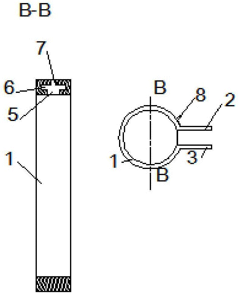
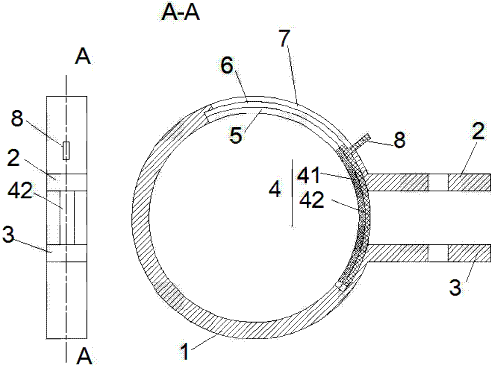
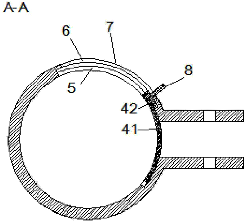
[0020] refer to figure 1 , figure 2 , a joint fastener for an oil cooler proposed by the present invention includes: a hoop 1 , a first pressure plate 2 , a second pressure plate 3 and a seal 4 .

[0021] The hoop 1 is an open ring structure, the first pressure plate 2 and the second pressure plate 3 are respectively connected to the first end and the second end of the hoop 1 and are located outside the hoop 1, the first pressure plate 2 and the second pressure plate 3 are parallel to each other, The first pressing plate 2 and the second pressing plate 3 are respectively provided with perforations, and the positions of the perforations are corresponding. When the hoop 1 is set on the position that needs to be tightened, such as the joint between the oil cooler and the oil tank, the first pressure plate 2 and the second pressure plate 3 can be locked by bolts, and the joint can be pressed tightly through the hoop 1 .

[0022] The inner wall of the hoop 1 is provided with a f...


PUM


Abstract

A joint fastener for an oil cooler proposed by the present invention includes: a hoop, a first pressing plate, a second pressing plate and a sealing body. The joint fastener of the oil cooler disclosed by the present invention, when used for the joint of the oil cooler and the oil tank, realizes disassembly and connection, which is convenient for maintenance; the 360-degree seamless pressure is formed by the head hoop and the sealing plate, which ensures the joint The tightness of the place.

Description

technical field [0001] The invention relates to the technical field of auto parts manufacturing, in particular to an oil cooler joint fastener. Background technique [0002] As an accessory used to connect the oil cooler and the oil tank in auto parts, the oil cooler joint requires good sealing and durability. At present, the joints of oil coolers focus on tightness. There are countless products on the market that increase the tightness of oil cooler joints by various means, but these products are not easy to repair during use. Contents of the invention [0003] Based on the technical problems existing in the background technology, the present invention proposes a joint fastener for an oil cooler. [0004] A joint fastener for an oil cooler proposed by the present invention includes: a hoop, a first pressing plate, a second pressing plate and a sealing body; [0005] The hoop is an open ring structure, the first pressure plate and the second pressure plate are respective...

Claims


Application Information

Patent Timeline
Patent Type & Authority Applications(China)
IPC IPC(8): F16L21/06
CPCF16L21/065
Inventor 李林峰
Owner 安徽凯瑞汽配制造有限公司
Why Eureka
Try Eureka