Ultrahigh-speed tensile testing machine driven by rocket engines

A rocket engine and tensile testing machine technology, applied in the direction of applying stable tension/pressure to test the strength of materials, instruments, measuring devices, etc., can solve the problems of high elongation, slow loading speed, limited loading stroke, etc., to achieve Large pulling force, short loading time and good versatility

Active Publication Date: 2017-06-09
NANJING UNIV OF SCI & TECH
View PDF7 Cites 4 Cited by
  • Summary
  • Abstract
  • Description
  • Claims
  • Application Information

AI Technical Summary

Problems solved by technology

[0004] The technical problem to be solved by the present invention is to provide an ultra-high-speed tensile testing machine driven by a rocket engine, so as to solve the problem of slow loading speed caused by the small power of the motor of the current tensile testing machine, and the limitation of the loading stroke and the inability to test the relatively high elongation rate. The problem of high material; the tensile testing machine of the present invention is driven by the rocket engine, realizes the short-term ultra-high-speed tensile test of the material, and can adjust the stretching stroke at the same time, and is suitable for the performance of the short-term ultra-high-speed loading of the material analyze

Method used


Image

  • Ultrahigh-speed tensile testing machine driven by rocket engines
  • Ultrahigh-speed tensile testing machine driven by rocket engines
  • Ultrahigh-speed tensile testing machine driven by rocket engines

Examples


Embodiment Construction

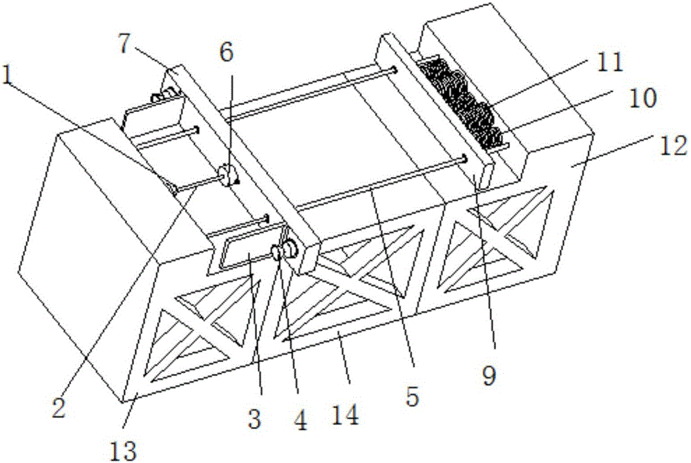
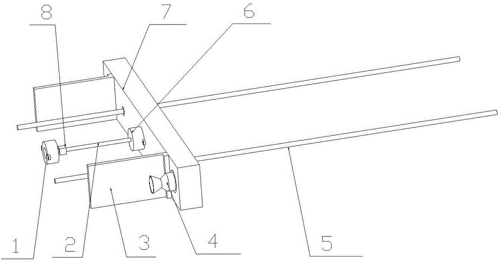
[0016] combine figure 1 , figure 2 , a rocket engine-driven ultra-high-speed tensile testing machine of the present invention includes a workbench, a stretching device, a driving device, a deceleration device, and a guide rail 5; the stretching device includes a first clamp 1, a second clamp 6 and a slide plate 7; the driving device includes a rocket motor 4; the guide rail 5 is fixed on the upper end of the workbench; the first clamp 1 is fixed on one end of the upper end of the workbench, and the first clamp 1 is used for clamping One end of the sample to be tested, the deceleration device is fixed on the other end of the upper end of the workbench, which is used for buffering and protecting the impact of the stretching device; the second clamp 6 is fixed on the slide plate 7, and the second clamp 6 is used for clamping Hold the other end of the sample to be tested, the connection line between the first clamp 1 and the second clamp 6 is parallel to the length direction of ...


PUM

PropertyMeasurementUnit
lengthaaaaaaaaaa
elongation at breakaaaaaaaaaa
elongationaaaaaaaaaa

Abstract

The invention discloses an ultrahigh-speed tensile testing machine driven by rocket engines. The ultrahigh-speed tensile testing machine comprises a workbench, a stretching device, a driving device, a reduction gear, and a guide slide rail, wherein the stretching device comprises a first clamp, a second clamp and a sliding plate; the driving device comprises the rocket engines; the guide slide rail is fixed at the upper end of the workbench; the first clamp is fixed at one end of the upper end of the workbench, and the reduction gear is fixed at the other end of the upper end of the workbench; the second clamp is fixed on the sliding plate and used for clamping the other end of a tested sample, and a connecting line between the first clamp and the second clamp is parallel to a length direction of the guide slide rail; the sliding plate slides linearly on the guide slide rail; and the rocket engines are symmetrically fixed at two ends of the sliding plate. The tensile testing machine provided by the invention can implement a short-time ultrahigh-speed tensile test for a material, can adjust the stretching stroke at the same time, and is suitable for performance analysis of short-time ultrahigh-speed loading of a material.

Description

technical field [0001] The invention belongs to material tensile testing equipment, in particular to a super high-speed tensile testing machine driven by a rocket engine. Background technique [0002] Tensile testing machine is a kind of tensile fracture test for long samples such as steel cables, chains and hoisting belts of various materials. It is widely used in metal products, building structures, ships, military industries and other fields. For materials such as flexible ropes and steel cables, such as bridge suspension cables and elevator traction wire ropes, in practical applications, they may be loaded with high-intensity tensile loads in a short period of time, which has a certain impact on the tensile strength of the materials. Requirements, this requires the determination of the tensile limit of the material. Therefore, a testing machine for ultra-high-speed tensile testing of materials is invented. By applying ultra-high-speed tensile force to materials in a sho...

Claims


Application Information

Patent Timeline
Patent Type & Authority Applications(China)
IPC IPC(8): G01N3/10
CPCG01N3/10G01N2203/0017G01N2203/0044G01N2203/0067G01N2203/028
Inventor 王健马超仇裕成李阳王吉
Owner NANJING UNIV OF SCI & TECH
Why Eureka
Try Eureka