Pot cover and pressure cooking appliance
A technology of cooking utensils and pot lids, which is applied to pressure cookers and other directions, can solve problems such as collision, misalignment, and damage to pressure cooking utensils, and achieve the effect of smooth lid closing, avoiding interference and collision, and improving experience
- Summary
- Abstract
- Description
- Claims
- Application Information
AI Technical Summary
Problems solved by technology
Method used
Image

Examples
Embodiment 1
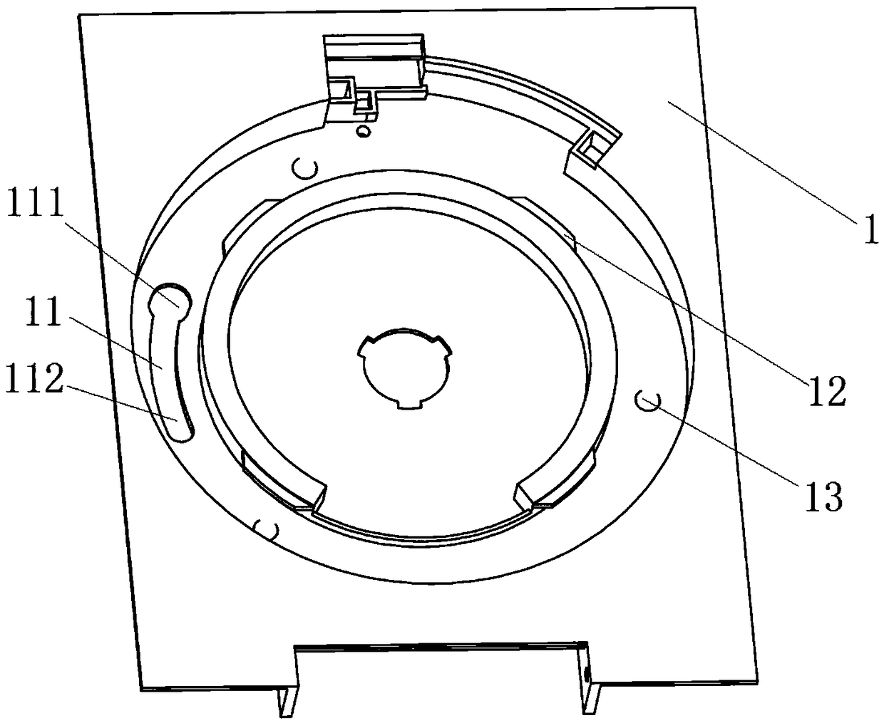
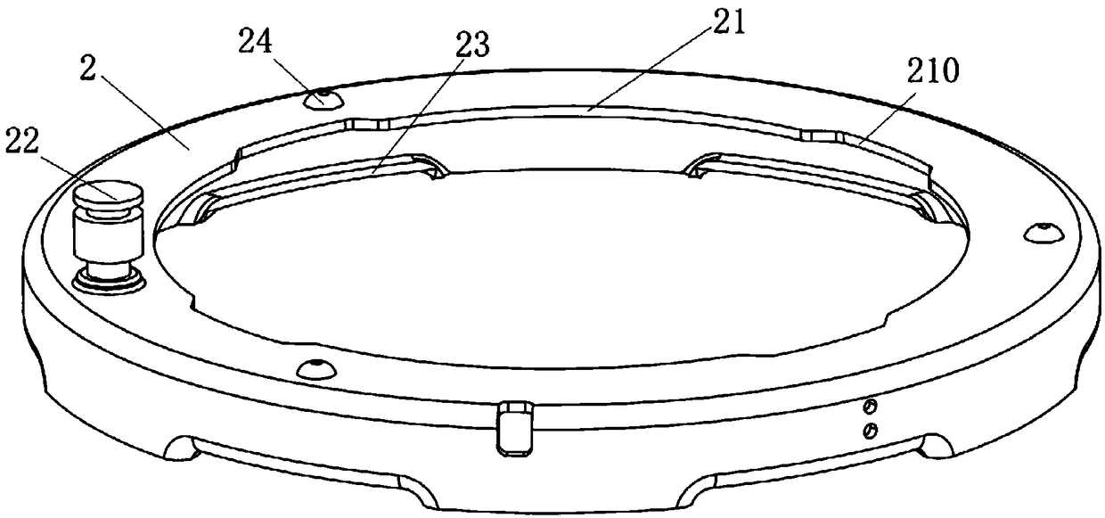
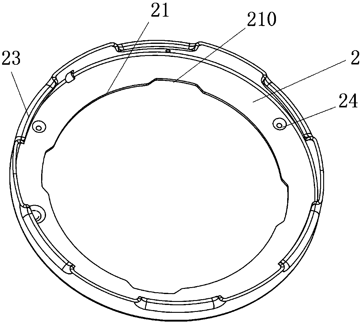
[0062] This embodiment provides a pot cover, which is used on a pressure cooking appliance; wherein, such as figure 1 , figure 2 , image 3 , Figure 5 and Figure 10 As shown, the pot cover in this embodiment includes a loam cake 1, a screw cap 2 and a limiting mechanism. Wherein, the screw cap 2 is arranged on the upper cover 1 . The limit mechanism is used to limit the screw cap 2 on the upper cover 1 so that the screw cover 2 cannot rotate relative to the upper cover 1 . Wherein, when the pot cover in this embodiment is fastened on the pot body of the cooking utensil, the cooking utensil is in a closed state (ie, a sealed and pressure-bearing state) by rotating the screw cap 2 . After the cooking utensil is uncapped (that is, the pot cover is not fastened on the pot body), the limiting mechanism limits the position of the rotary cover 2 so that the rotary cover 2 cannot rotate relative to the upper cover.
[0063] Preferably, the upper cover 1 in this embodiment and...
Embodiment 2
[0066] Preferably, this embodiment provides a pot cover, compared with the previous embodiment, such as figure 1 and figure 2 , Figure 5 to Figure 14 As shown, the present embodiment carries out the following design to the limit mechanism:
[0067] The limiting mechanism in this embodiment includes: a slide groove 11 , a sliding structure 22 and a stop structure. Wherein, the chute 11 is provided on the upper cover 1 . The sliding structure 22 is arranged on the rotating cover 2, wherein, when the sliding structure 22 slides in the chute 11, the rotating cover 2 rotates relative to the upper cover 1 (here, the chute can also be arranged on the rotating cover, and the sliding structure Correspondingly arranged on the upper cover; however, in this embodiment, the chute is preferably arranged on the upper cover, and the sliding structure is arranged on the rotating cover, so that it is beneficial for the user to control the sliding structure through the handle, and then cont...
Embodiment 3
[0070] Preferably, this embodiment provides a pot cover, compared with Embodiment 2, such as figure 1 , figure 2 , Figure 4 to Figure 14 As shown, the present embodiment further designs the sliding structure 22 as follows:
[0071] The sliding structure 22 in this embodiment has a first end 221 and a second end 222 . Wherein, the first end 221 is an end arranged on the sliding structure 22 close to the screw cap 2; the second end 222 is an end arranged on the sliding structure 22 away from the screw cover 2 (that is, an end arranged close to the upper cover 1); and, The diameter of the second end 222 is greater than the diameter of the first end 221 .
[0072] Correspondingly, the sliding slot 11 includes a limiting hole 111 disposed at one end of the sliding slot 11 and a limiting slot 112 communicating with the limiting hole 111 . Wherein, the diameter of the limiting hole 111 is not smaller than the diameter of the second end 222 of the sliding structure 22 , so that ...
PUM
 Abstract
Description
Claims
Application Information
 - R&D
- Intellectual Property
- Life Sciences
- Materials
- Tech Scout
- Unparalleled Data Quality
- Higher Quality Content
- 60% Fewer Hallucinations
Browse by: Latest US Patents, China's latest patents, Technical Efficacy Thesaurus, Application Domain, Technology Topic, Popular Technical Reports.
© 2025 PatSnap. All rights reserved.Legal|Privacy policy|Modern Slavery Act Transparency Statement|Sitemap|About US| Contact US: help@patsnap.com