Cast-in-place pile with positioning device combined steel formwork and its construction method

A technology of positioning device and construction method, which is applied in the direction of sheet pile wall, foundation structure engineering, building, etc., can solve problems such as spacing deviation, achieve the effects of controllable elevation and axis deviation, accurate positioning, and reduce mold swelling

Active Publication Date: 2019-01-08
SEPCOIII ELECTRIC POWER CONSTR CO LTD
View PDF6 Cites 0 Cited by
  • Summary
  • Abstract
  • Description
  • Claims
  • Application Information

AI Technical Summary

Problems solved by technology

[0003] The purpose of the present invention is to overcome the shortcomings in the prior art. First, it provides a positioning device combined steel formwork cast-in-place pile. The cast-in-place pile positioning bracket solves the problem of spacing deviation between pile foundations, and at the same time, the elevation of the embedded parts is easy to control. Secondly, a construction method for cast-in-place piles is also provided, which reduces errors caused by manual operations and makes the quality easier to control. The technical solution adopted is: a positioning device combined steel formwork cast-in-place pile, including a pile foundation positioning device and connection The steel formwork on the positioning device, the cast-in-place pile is formed by pouring concrete into the steel formwork and vibrating it. It is characterized in that: the positioning device includes: a positioning bracket, and the positioning bracket includes a frame. There are template positioning holes; adjusting screw, one end of the adjusting screw is fixed on the ground, and the other end is processed with threads; adjusting wire sleeve, the adjusting wire sleeve is fixed on the positioning bracket, and the inside of the wire sleeve There are internal threads matching the external threads on the adjustment screw; the steel template positioning bolts that match the template positioning holes are fixed on the steel template

Method used


Image

  • Cast-in-place pile with positioning device combined steel formwork and its construction method
  • Cast-in-place pile with positioning device combined steel formwork and its construction method
  • Cast-in-place pile with positioning device combined steel formwork and its construction method

Examples


Embodiment Construction

[0023] The specific implementation manners of the present invention will be described below in conjunction with the accompanying drawings.

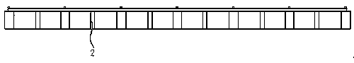
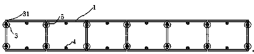
[0024] The invention firstly discloses a cast-in-place pile with a positioning device combined with a steel formwork, which includes a pile foundation positioning device and a steel formwork 3 connected to the positioning device. The cast-in-place pile is formed by pouring concrete into the steel formwork and vibrating it. The positioning device includes: a positioning bracket 1, the positioning bracket includes a frame, and a template positioning hole 31 is opened on the frame; an adjustment screw 2, one end of the adjustment screw 2 is fixed on the ground, and the other end is connected to the frame; The wire sleeve 4 is fixed on the positioning bracket 1, and the adjustment wire sleeve 4 is provided with an internal thread matched with the external thread on the adjustment screw 2. After adjusting the lead screw and the adjustment wire...


PUM


Abstract

The invention discloses a locating device combined steel template cast-in-place pile and a construction method. The cast-in-place pile comprises a pile foundation locating device and a steel template connected on the locating device, and the cast-in-place pile is formed through pouring concrete into the steel template and carrying out vibration, wherein the locating device comprises a locating bracket, adjusting screw rods and adjusting screw sleeves; the locating bracket comprises a frame; bolt locating holes are formed in the frame; one ends of the adjusting screw rods are fixed to the ground; the other ends of the adjusting screw rods are connected with the frame; the adjusting screw sleeves are fixed to the locating bracket; internal threads matched with external threads on the adjusting screw rods are formed in the screw sleeves; and steel template locating bolts matched with template locating holes are fixed to the steel template. According to the locating device combined steel template cast-in-place pile, location for a pile foundation is accurate, relative sizes among the piles are directly set through the locating device according to the design requirement, and the problem that the front-back and left-right intervals of the adjacent pile foundations are different is solved.

Description

technical field [0001] The invention relates to the technical field of bored cast-in-situ pile construction, in particular to a construction method of a positioning device combined steel formwork cast-in-place pile, in particular to a construction method of more than two rows of positioning device combined formwork cast-in-place piles and the cast-in-situ pile. Background technique [0002] In the construction of photovoltaic power stations, holes are directly drilled on the designed pile positions, and steel cages are placed in the holes after the holes are formed. The cast-in-situ pile foundation formed by pouring concrete plays a dominant role in various types of component support foundations. During the construction, it was found that because the traditional construction method used PVC formwork for the cast-in-place piles to be supported separately, and the spacing and elevation were controlled by hanging wires, it was difficult to control the spacing of the piles and th...

Claims


Application Information

Patent Timeline
Patent Type & Authority Patents(China)
IPC IPC(8): E02D5/38E02D15/04
CPCE02D5/38E02D15/04
Inventor 初玉明李福忠李成建冯涛冯红兵
Owner SEPCOIII ELECTRIC POWER CONSTR CO LTD
Why Eureka
Try Eureka