Eureka AIR delivers breakthrough ideas for toughest innovation challenges, trusted by R&D personnel around the world.

Operation platform of mining electromechanical equipment

A technology for operating platforms and mine electromechanical devices, applied in the direction of lifting devices, lifting frames, etc., can solve the problems of unadjustable jacks, heavy support platforms, inconvenient movement or transportation, etc., and achieve the effect of solving the inconvenience of movement and transportation

Inactive Publication Date: 2017-06-20
CHONGQING SHANGSHANG SCI & TECH CO LTD
View PDF1 Cites 4 Cited by
  • Summary
  • Abstract
  • Description
  • Claims
  • Application Information

AI Technical Summary

Problems solved by technology

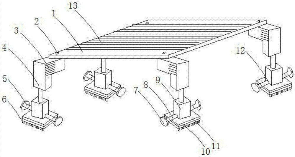
[0002] At present, when mining machinery is in operation, it is necessary to flatten and fix the bottom surface of the mining machinery. , the terrain needs to be leveled first, which is time-consuming and labor-intensive. At the same time, the general mine electromechanical equipment operation support platform is relatively heavy, and there are problems of inconvenient movement or transportation. For example, the patent application number 201420230121. If the jack is installed, the support platform can be placed horizontally, but the position of the jack is indeed fixed, and the position of the jack cannot be adjusted. In places with relatively bad terrain, it is particularly difficult to support it, which is not very practical, and the connection between the support platform and the jack is used The connecting rod, because the mining machinery is relatively heavy, the connection between the jack and the support table may not be supported, resulting in damage to the connecting rod, which will cause the mining machinery to fall and be damaged

Method used


Image

  • Operation platform of mining electromechanical equipment

Examples


Embodiment Construction

[0012] The following will combine this Invention In the example Attached picture , to this Invention The technical solutions in the embodiments are described clearly and completely. Obviously, the described embodiments are only the present invention. invention Some, but not all, embodiments. Based on this invention All other embodiments obtained by persons of ordinary skill in the art without creative work belong to the present invention. invention scope of protection.

[0013] see picture 1 ,Book invention Provide a technical solution: A mining electromechanical equipment operating platform , comprising a support platform 1, the top of the support platform 1 is provided with an anti-slip strip 13 to prevent mechanical equipment from slipping, the four corners of the inner cavity of the support platform 1 are provided with connecting rods 2, and the bottom ends of the four corners of the support platform 1 are A support arm 4 is provided, and the outer wall of th...


PUM


Abstract

The invention discloses an operation platform of mining electromechanical equipment. The operation platform comprises a supporting table, wherein connecting rods are separately arranged on four corners of an inner cavity of the supporting table; each supporting arm is arranged at the bottom end of each of four corners of the supporting table, and is movably connected with the supporting table through a connecting rod; a jack is arranged at the bottom end of each supporting arm; a groove is formed in the bottom end of each jack; a cylindrical shaft is mounted in an inner cavity of each groove; folding arms are separately arranged at the left end and the right end of each cylindrical shaft; pulleys are separately arranged at the left end and the right end of each folding arm; a decompressing cushion is arranged at the bottom end of each jack; and a supporting base is arranged at the bottom end of each decompressing cushion. According to the operation platform of mining electromechanical equipment disclosed by the invention, when the environment of mining machinery is adverse and the terrain is uneven, the supporting arms and the jacks are mounted at the bottom end of the supporting table, and the supporting table is level by adjusting the jacks; and besides, the pulleys are arranged at the left end and the right end of each folding arm, so that during moving and transporting, the operation platform can be pushed to slide, and the problem that the moving and the transporting are inconvenient is solved.

Description

technical field [0001] Book invention Involved in the field of mining machinery technology, specifically A mining electromechanical equipment operating platform . Background technique [0002] At present, when mining machinery is in operation, it is necessary to flatten and fix the bottom surface of the mining machinery. , the terrain needs to be leveled first, which is time-consuming and labor-intensive. At the same time, the general mine electromechanical equipment operation support platform is relatively heavy, and there are problems of inconvenient movement or transportation. For example, the patent application number 201420230121. If the jack is installed, the support platform can be placed horizontally, but the position of the jack is indeed fixed, and the position of the jack cannot be adjusted. In places with relatively bad terrain, it is particularly difficult to support it, which is not very practical, and the connection between the support platform and the jack...

Claims


Application Information

Patent Timeline
IPC IPC(8): B66F7/08B66F7/20
CPCB66F7/0625B66F7/08B66F7/20
Inventor 黄燕
Owner CHONGQING SHANGSHANG SCI & TECH CO LTD
Why Eureka
Eureka Blog
Learn More