Backlight unit and liquid crystal display device
A backlight module and backplane technology, applied in optics, nonlinear optics, instruments, etc., can solve the problems of large refractive index difference, reduce the number of laser lines emitted and light output efficiency, etc., to increase the number of light rays and improve the light output. The effect of efficiency
- Summary
- Abstract
- Description
- Claims
- Application Information
AI Technical Summary
Problems solved by technology
Method used
Image

Examples
Example Embodiment
[0040] Example 1
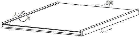
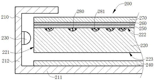
[0041] The first embodiment of the present invention provides a backlight module 200 , for its overall structure, please refer to Figure 2a As shown, in order to express the local structure of the quantum dot display panel 200 more clearly, along the Figure 2a After the section in the middle A direction and the partial enlargement at M, please refer to Figure 2b As shown, the backlight module 200 includes: a backplane 210, a light guide plate 220 disposed at the bottom of the backplane 210, a light source 230 disposed opposite the light incident surface of the light guide plate 220, a reflection sheet 240 disposed below the light guide plate 220, and The protective layer 250 , the refraction layer 260 and the diaphragm group 270 are placed above the light guide plate 220 and laminated in sequence.
[0042] Specifically, the back plate 210 includes a bottom plate 211 and a side wall 212 perpendicular to the edge of the bottom plate 211 , and the light gu...
Example Embodiment
[0059] Embodiment 2
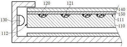
[0060] The second embodiment of the present invention provides another backlight module 200 . Please refer to the partial structure of the backlight module 200 . Figure 4a As shown, the components of the backlight module provided in this embodiment are the same as those of the backlight module provided in the first embodiment. The difference from the first embodiment is that in the second embodiment, the concave portion 280 encapsulated with the quantum dot material 281 is disposed on the lower surface 223 of the light guide plate 220, and the cover protective layer 250 is attached to the lower surface 223 to isolate the particles in the outside air. Moisture and oxygen, and the refractive layer 260 is laminated on the surface of the protective layer 250 , and the refractive index of the refractive layer 260 is between the protective layer 250 and the air layer. Wherein, the setting methods and functions of each part in this embodiment have been explain...
Example Embodiment
[0064] Embodiment 3
[0065] For a liquid crystal display device provided by the third embodiment of the present invention, please refer to Figure 5 As shown, the liquid crystal display device 300 includes the backlight module 200 provided in the first embodiment or the second embodiment, and further includes: a display panel 301 placed above the backlight module 200, and a white color provided by the backlight module 200 The backlight completes the screen display.
[0066] To sum up, the present application provides a backlight module and a liquid crystal display device, wherein, in the backlight module provided, a recessed portion encapsulated with quantum dot materials is opened on the surface of the light guide plate, and is connected with the lower surface. The protective layer arranged by bonding realizes the encapsulation of the quantum dot material to isolate oxygen and moisture in the external environment, and a plurality of refractive layers are laminated and lamin...
PUM
 Abstract
Description
Claims
Application Information
 - Generate Ideas
- Intellectual Property
- Life Sciences
- Materials
- Tech Scout
- Unparalleled Data Quality
- Higher Quality Content
- 60% Fewer Hallucinations
Browse by: Latest US Patents, China's latest patents, Technical Efficacy Thesaurus, Application Domain, Technology Topic, Popular Technical Reports.
© 2025 PatSnap. All rights reserved.Legal|Privacy policy|Modern Slavery Act Transparency Statement|Sitemap|About US| Contact US: help@patsnap.com