Gas injector with non-elastomer seal seat

A gas injector and sealing seat technology, which is used in machines/engines, charging systems, combustion engines, etc., can solve problems such as valve needle acceleration, sealing seat strength loss, valve needle vibration, etc.

Active Publication Date: 2021-05-14
ROBERT BOSCH GMBH
View PDF6 Cites 0 Cited by
  • Summary
  • Abstract
  • Description
  • Claims
  • Application Information

AI Technical Summary

Problems solved by technology

But this requires large actuators or actuators with expensive materials
High sealing forces also cause strong accelerations of the valve needle or the like, which cause high losses on the sealing seat and cause high noise generation and chattering of the valve needle

Method used


Image

  • Gas injector with non-elastomer seal seat
  • Gas injector with non-elastomer seal seat
  • Gas injector with non-elastomer seal seat

Examples


Embodiment Construction

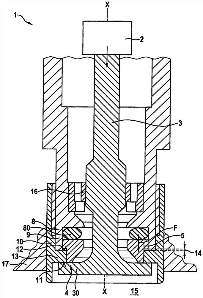
[0023] Subsequent reference figure 1 and figure 2 Details A gas injector 1 according to a first preferred embodiment of the invention is described.

[0024] Such as figure 1 As stated, the gas injector 1 comprises an actuator 2 , which is only shown schematically. The actuator 2 is connected to a valve mechanism 3 , in this embodiment a valve needle with a valve disk 30 .

[0025] The valve mechanism 3 is also guided by means of a guide element 16 .

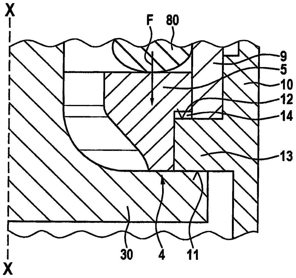
[0026] The gas injector 1 also includes a sealing seat 4 which is arranged between the movable sealing element 5 and the valve disk 30 . The sealing seat 4 is a flat sealing seat and is arranged as far as possible on the outer periphery of the valve disk 30 . Furthermore, a first stop 11 is arranged on the annular region 13 of the housing sleeve 10 . The first stop 11 is a metallic stop between the valve disk 30 and the annular region 13 . The first stop 11 is here radially outside the sealing seat 4 . The second stop 12...


PUM


Abstract

The invention relates to a gas injector for blowing a gaseous medium, comprising: an actuator (2); a valve mechanism (3); a seal between said valve mechanism (3) and a sealing element (5) seat (4); a first stop (11), against which the valve mechanism (3) rests in the closed state of the gas injector; and a pretensioning device (8), the The pretensioning device pretensions the sealing element (5) along the axial direction (X-X) of the gas injector, wherein the sealing element (5) is a non-elastomeric sealing element.

Description

technical field [0001] The invention relates to a gas injector for injecting a gaseous medium, in particular a gaseous fuel, which has an elastomer-free sealing seat. Furthermore, the invention relates to an internal combustion engine having a gas injector according to the invention, in particular for injecting gaseous fuel directly into a combustion chamber of the internal combustion engine. Background technique [0002] Gaseous fuels, especially for vehicles, have become more and more popular recently, especially on the basis of cost advantages. For consumption and exhaust gas reasons, so-called direct injection is also advantageously provided in this case, in which the gas injector is arranged directly on the combustion chamber of the internal combustion engine. In this case, however, the gas injector is subjected to very high temperatures, so that a seal of the gas injector on the sealing seat is not possible in the closed state by means of conventional elastomers. The...

Claims


Application Information

Patent Timeline
Patent Type & Authority Patents(China)
IPC IPC(8): F02M21/02
CPCF02M21/0248F02M21/0251F02M21/0257F02M21/0269Y02T10/30
Inventor F·莫泽M·诺尔普O·舍恩罗克S·克里斯勒
Owner ROBERT BOSCH GMBH
Why Eureka
Try Eureka