Case function module test fixture

A technology of functional modules and test tooling, applied in the direction of measuring device, measuring device casing, measuring electricity, etc., can solve problems such as inability to adapt to dynamic environmental tests

Active Publication Date: 2017-06-23
CHINA AVIATION OPTICAL-ELECTRICAL TECH CO LTD
View PDF6 Cites 11 Cited by
  • Summary
  • Abstract
  • Description
  • Claims
  • Application Information

AI Technical Summary

Problems solved by technology

[0005] The purpose of the present invention is to provide a test tool for the functional module of the chassis to solve the problem that the existing test method cannot adapt to the dynamic environment test

Method used


Image

  • Case function module test fixture
  • Case function module test fixture
  • Case function module test fixture

Examples


Embodiment Construction

[0023] The present invention will be further described below in conjunction with accompanying drawing.

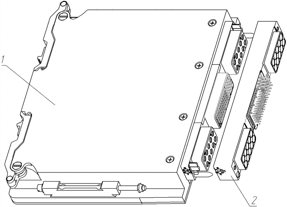
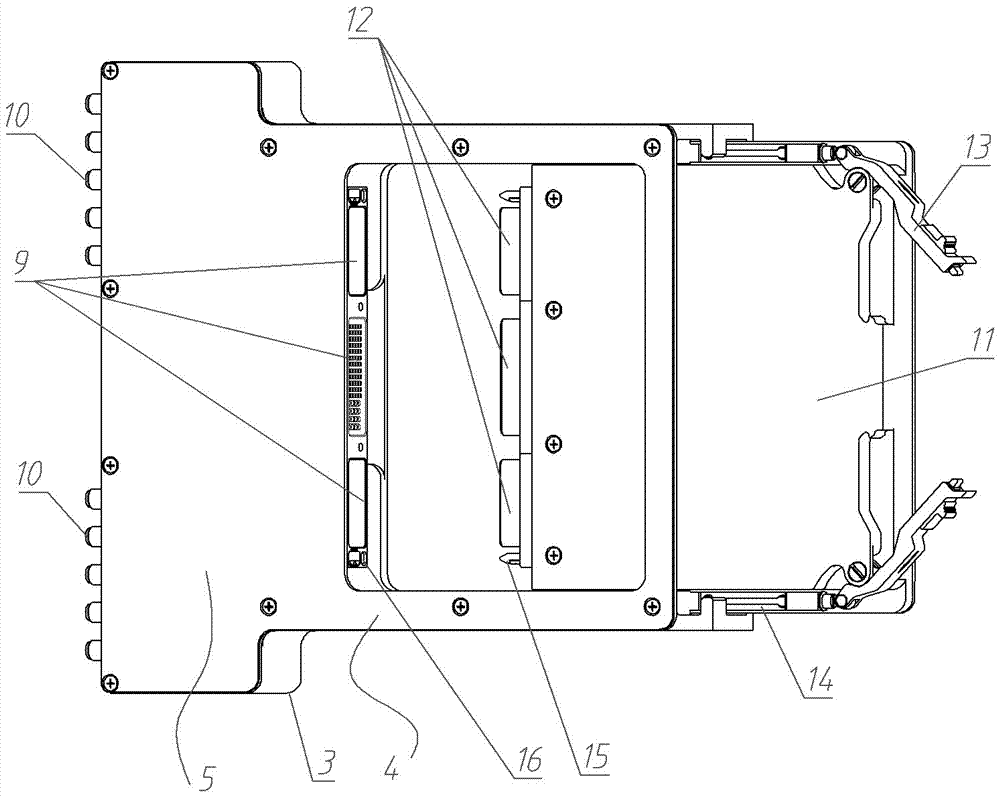
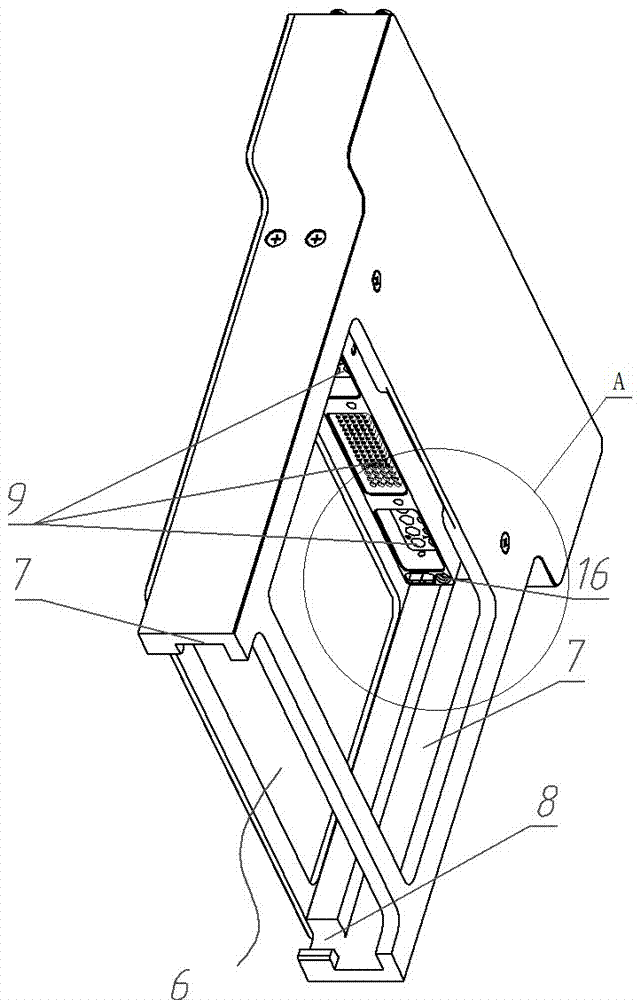
[0024] An embodiment of the test tool for the chassis function module of the present invention is as follows: Figure 2~Figure 5 As shown, the tooling main body 3 is included, and the tooling main body 3 is a cuboid as a whole, including a frame part 4 and a box body part 5 arranged in sequence along the insertion direction of the functional module to be tested, and the frame part 4 is provided with a functional module 1 to be tested. The inserted slot 6 is provided with a chute 7 on the groove wall of the slot 6, and the chute 7 forms a guide rail for guiding and cooperating with the guide structure on the functional module 1 to be tested. The module connector 12 on the test function module 1 is mated with the test connector 9 and the signal lead-out terminal 10 for test signal lead-out along the guiding direction of the guide rail. The width of the box body part 5 is lar...


PUM


Abstract

The invention relates to a case function module test fixture. The test fixture comprises a fixture body. The fixture body is provided with a slot for a to-be-tested function module to be inserted into. A guide rail used for being in guide fit with a guide structure on the to-be-tested function module is arranged on the slot. The fixture body is further provided with a test connector used for being in insertion fit with a module connector on the to-be-tested function module along the guide direction of the guide rail, and a locking structure used for locking the to-be-tested function module inserted in place onto the fixture body. The test connector is connected with a signal lead-out terminal for leading out a test signal. The fixture can simulate the situation in which the to-be-tested function module is inserted into a slot of a case, and facilitates insertion fit between the test connector and the module connector. In addition, the fixture body is further provided with the locking structure used for locking the to-be-tested function module inserted in place onto the fixture body, so that the to-be-tested function module inserted in place can be firmly fixed on the test fixture, and dynamical environment test can be conducted.

Description

technical field [0001] The invention relates to a testing tool for a functional module of a chassis. Background technique [0002] At present, modularized chassis are widely used in large-scale systems. For example, a modularized chassis disclosed in the Chinese patent application publication number CN105960132 A includes a front panel, left and right side panels, upper and lower cover panels and a rear panel. The main body of the chassis, the front side of the main body of the chassis is provided with a card insertion port for the insertion and extraction of functional modules, the upper and lower covers are provided with guide rails for guiding the front and rear insertion and removal of functional modules, and the rear panel is set on the back panel. There are backplane connector sockets. The functional module is in the form of a card, and its upper and lower sides are provided with guiding structures that cooperate with the guide rails. The front end is provided with a ...

Claims


Application Information

Patent Timeline
Patent Type & Authority Applications(China)
IPC IPC(8): G01R1/04G01R31/00
Inventor 张小虎潘娟娟
Owner CHINA AVIATION OPTICAL-ELECTRICAL TECH CO LTD
Why Eureka
Try Eureka