
Gear pump with phase dislocation gear compensation structures

A compensation structure and gear pump technology, applied to rotary piston type/oscillating piston type pump components, pumps, pump elements, etc., can solve the problem of large output flow pulsation, reduce output pulsation amplitude, improve stability, and improve flow rate The effect of output improvement

Inactive Publication Date: 2017-06-27
皮桂庆
View PDF8 Cites 2 Cited by
  • Summary
  • Abstract
  • Description
  • Claims
  • Application Information

AI Technical Summary

Problems solved by technology

[0003] The purpose of the present invention is to provide a gear pump with an out-of-phase gear compensation structure to reduce the problem of large output flow pulsation of the existing gear pump

Method used


Image

  • Gear pump with phase dislocation gear compensation structures
  • Gear pump with phase dislocation gear compensation structures
  • Gear pump with phase dislocation gear compensation structures

Examples


Embodiment 1

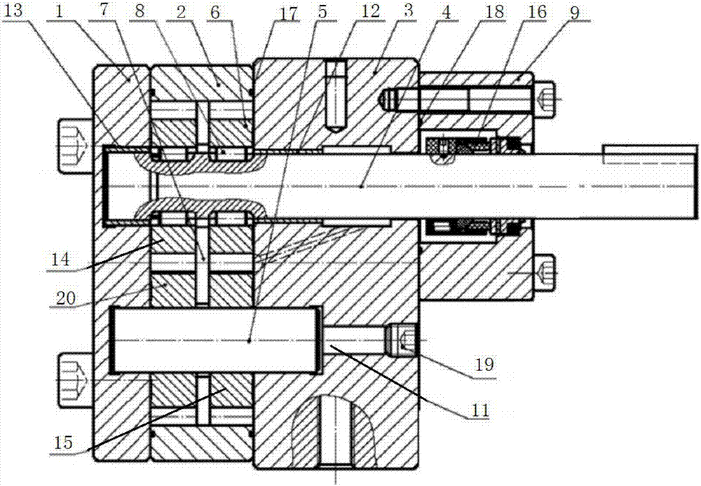
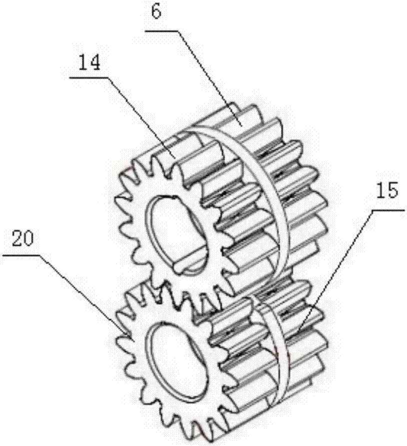
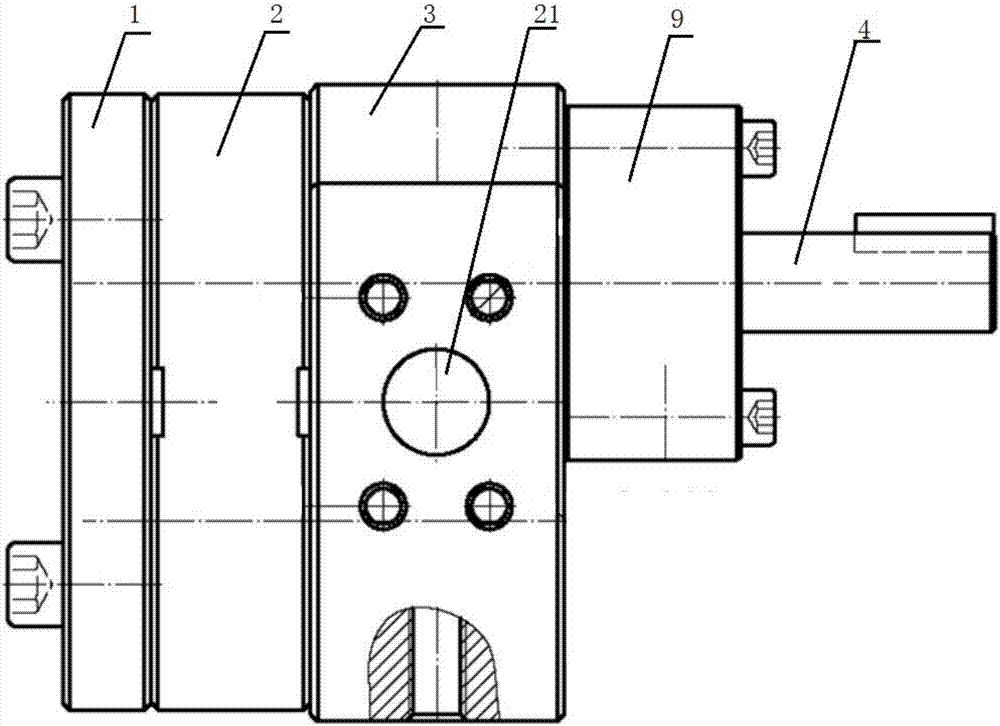
[0033] combine Figure 1~3 , the gear pump with the out-of-phase gear compensation structure mainly includes a pump body and two sets of meshing gear sets arranged in the pump body, the driving gear of the meshing gear set is fixed on the main shaft 4, and the driven gear of the meshing gear set is installed on the pin shaft 5 One end of the pin shaft 5 is fixed inside the front pump plate 3 of the pump body, and the other end is assembled with the rear pump plate 1 of the pump body. A partition 7 is arranged between adjacent meshing gear groups, and the partition 7 makes each meshing gear The two sets of gears form an independent working chamber to ensure the normal operation of each meshing gear set. The positions of the teeth of each driving gear are staggered to form a phase difference, thereby forming a complementarity. In this way, when the materials are discharged from the two pairs of gears, the pulsation waves formed by each are just opposite. , and compensate each ot...


PUM


Abstract

The invention discloses a gear pump with phase dislocation gear compensation structures. The gear pump comprises a pump and two meshing gear trains. The meshing gear trains are arranged in the pump, driving gears of the meshing gear trains are fixed onto spindles, driven gears of the meshing gear trains are mounted on hinge pins, one end of each hinge pin is fixed to the inner side of a front pump plate of the pump, the other end of each hinge pin is fittingly assembled with a rear pump plate of the pump, partition plates are arranged between the adjacent meshing gear trains, the locations of teeth of the gears of the two trains are staggered to form phase difference so as to realize complementary effects. The gear pump has the advantages that pulse waves formed by materials are exactly opposite to one another when the materials are discharged from the gears of the two trains and are compensated by one another after the materials flow together, output flow pulses of the gear pump can be effectively reduced, and accordingly the stability of the gear pump can be obviously improved; output pulse amplitude of existing conventional gear pumps can be effectively lowered to a great extent by the aid of the simplest methods at the lowest cost, and accordingly flow can be stably outputted by the gear pump.

Description

technical field [0001] The invention relates to the technical field of gear pumps, in particular to a gear pump with a phase-staggered gear compensation structure. Background technique [0002] Conventional gear pumps are composed of a pair of gears meshing with each other and a pump body closely matched with them. When the material is discharged from the meshing gear, the output flow will pulsate and the stability is poor. At present, in order to reduce the output pulsation amplitude of the gear pump and improve the stability of the material output, there are mainly the following two methods: 1. Increase the number of teeth, but it will increase the volume and weight of the pump with the same displacement, resulting in material waste and increased cost. . 2. Changing straight teeth to helical teeth will increase the difficulty of processing and increase the processing cost. At the same time, the helical gears will generate axial force when meshing, which will increase the...

Claims


Application Information

Patent Timeline
Patent Type & Authority Applications(China)
IPC IPC(8): F04C2/18F04C15/00
CPCF04C2/18F04C15/00F04C2240/20
Inventor 皮桂庆杨险峰
Owner 皮桂庆
Learn More