

Electric pressure cooker with cover being conveniently opened
An electric pressure cooker, a convenient technology, applied in the direction of pressure cooker, cooking utensils, household utensils, etc., can solve the problems of inconvenient use and lower user experience, and achieve the effect of cost saving, simple structure and convenient use
- Summary
- Abstract
- Description
- Claims
- Application Information
AI Technical Summary
Problems solved by technology
Method used
Image

Examples
Embodiment 1
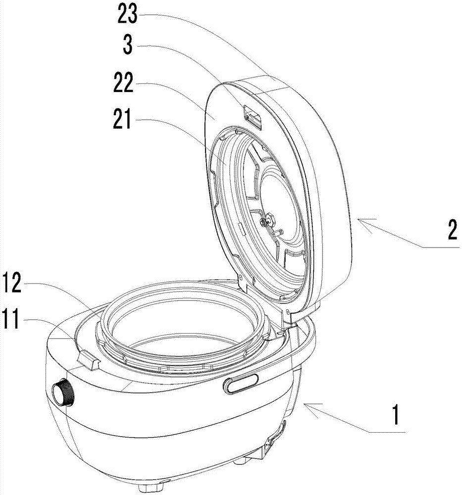
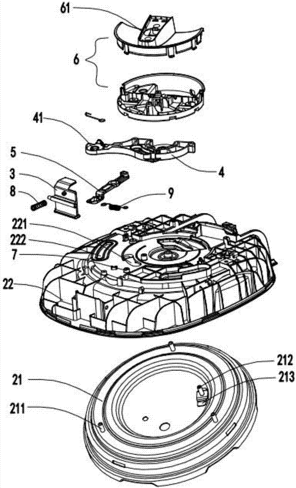
[0037] The invention provides an electric pressure cooker which is convenient to open the cover, please refer to Figure 1-Figure 7, comprising a pot body 1, a pot cover 2 and a buckle, the buckle includes a movable clip 3 arranged on the pot cover 2 and a fastener 11 positioned on the pot body 1, and the pot cover 2 is connected to the pot body through the buckle The pot body 1 is fastened, and the pot cover 2 includes a lining 22 and a lock cover 21 located below the liner 22. The lock cover 21 rotates to realize the locking and unlocking of the lock cover 21 and the pot body 1. The pot cover 2 also There is an opening assembly, which drives the lock cover 21 to rotate, and the lock cover 21 is provided with an unlocking member 212, and when the cover opening assembly drives the lock cover 21 to rotate to the first set position, the lock cover 21 and the pot body 1 are unlocked , when the cover opening assembly drives the lock cover 21 to continue to rotate to the second set...
Embodiment 2
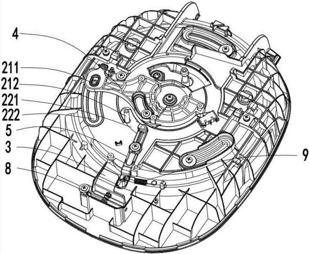
[0051] The difference between this embodiment and the first embodiment mainly lies in the structure of the unlocking part 212 on the lock cover 21 . In this example, if Figure 8-10 As shown, the unlocking member 212 is arranged on the lock cap post 211 . Specifically, the lock cover column 211 extends to the upper surface of the inner liner 22 after passing through the second escape groove 222 on the inner liner 22, and the shift fork member 4 is provided with a through hole 41, and the lock cover column 211 passes through the shift fork. The through hole 41 of the piece 4 is set. The rotation of the shift fork 4 can therefore drive the lock cover 21 to rotate. The lock cover column 211 is provided with a threaded hole, and the lock cover column 211 passes through the through hole 41 of the shift fork 4 and is fixed with a screw, and the unlocking member 212 is fixed between the nut and the shift fork 4 . And the unlocking part 212 is provided with a through hole, and the ...
Embodiment 3
[0053] The difference from Embodiment 1 is that in this embodiment, the lock cover is a lock ring, the pot body includes an inner container, and the pot cover also includes an inner cover, and the inner cover and the inner container are sealed to form a cooking cavity. A sealing ring is arranged between the cover and the inner container. The pot teeth are arranged on the inner container, and the cover teeth are arranged on the lock ring.
PUM
 Abstract
Description
Claims
Application Information