Printer with automatic back-off cutter structure and automatic back-off method of printer

A printer, automatic technology, applied in the direction of printing device, printing, etc., can solve the problem of fixed blades biting each other, achieve reliable release, and reduce the effect of recording paper jamming

Active Publication Date: 2017-07-07
XIAMEN HANIN ELECTRONICS TECH CO LTD
View PDF6 Cites 1 Cited by
  • Summary
  • Abstract
  • Description
  • Claims
  • Application Information

AI Technical Summary

Problems solved by technology

However, the fixed blade and the movable blade often bite each other due to jamming of the recording paper when the recording paper is cut

Method used


Image

  • Printer with automatic back-off cutter structure and automatic back-off method of printer
  • Printer with automatic back-off cutter structure and automatic back-off method of printer
  • Printer with automatic back-off cutter structure and automatic back-off method of printer

Examples


Embodiment 1

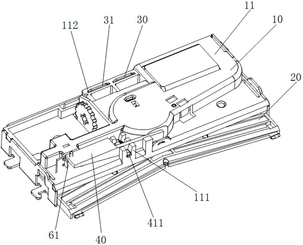
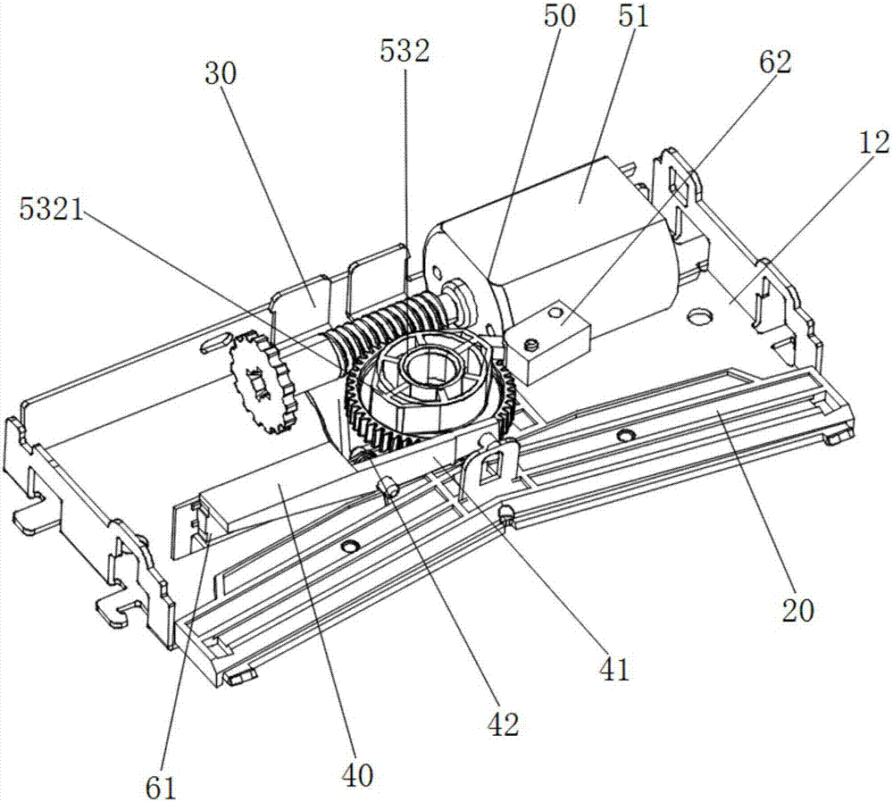
[0034] A printer capable of printing on recording paper pulled from a paper roller, and appropriately cutting the recording paper to use it as a ticket, receipt, etc. The printer mainly includes an integral housing structure, a flattening unit, and a main unit. The flattening unit includes a fixed blade and a matching cooperation mechanism. The design focus of this case is mainly on the main unit, please refer to figure 1 with image 3 The main unit includes a movable blade 20, a pre-tensioning mechanism 30, a driving system 50 and a release mechanism.

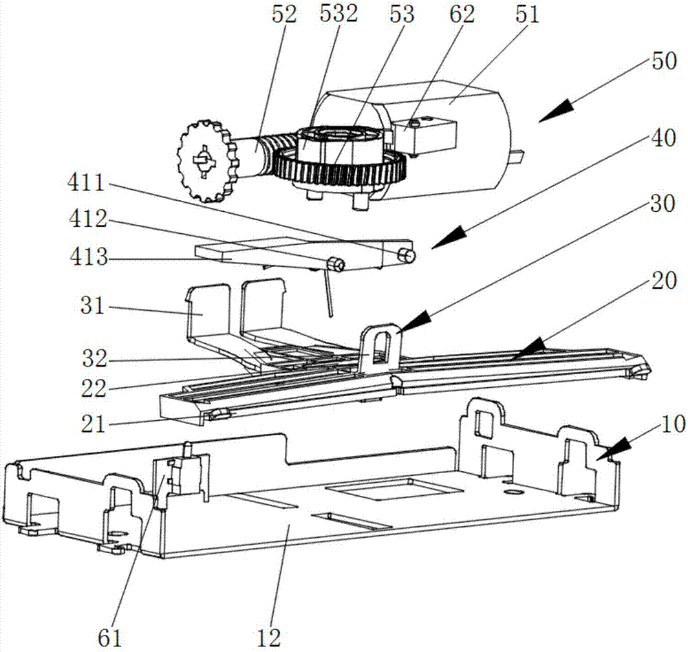
[0035] Please refer to figure 1 with figure 2 In the integral casing structure, there is a casing 10 for accommodating or assembling the main unit, and the casing 10 is a casing molded from a plastic or metal material. The casing 10 includes an inner casing and an outer casing 11. The inner casing and the outer casing 11 are combined to form a cavity. The main unit is arranged in the cavity or installed on the inner casing and ...

Embodiment 2

[0046] The difference between the second embodiment and the first embodiment is that the structure of the release mechanism used is different, and the pre-tensioning mechanism 30, the casing 10, etc. have been adapted to change.

[0047] Please refer to Figure 4 with Figure 5 In Embodiment 2, the release mechanism includes a push rod 41a and a connecting piece 43a, and the connecting piece 43a is arranged in the middle of the push rod 41a. The connecting piece 43a adopts a spring structure, and has two connecting pieces 43a respectively connected to the pre-tensioning mechanism 30, so that the connection stability is better and the linkage is more effective during startup. In this embodiment, the pre-tightening mechanism 30 does not need to be provided with a hooking portion 32, and the casing 10 is provided with a hollow protection column corresponding to the connecting piece 43a, and the protection column is provided with a relief groove along the pushing and returning directi...

Embodiment 3

[0050] Applying the printers in Embodiments 1 and 2 to realize the automatic fallback method includes the following steps:

[0051] S1. The release mechanism is activated, and the release mechanism linkages the pretensioning mechanism 30 to disengage the action on the movable blade 20, and the contact pressure between the movable blade 20 and the fixed blade is released:

[0052] Specifically, when the bite between the fixed blade and the movable blade 20 occurs, manually push or press the release mechanism; subsequently, the release mechanism pulls the pre-tensioning mechanism 30 to release it from pressing against the movable blade 20 This function allows the contact pressure between the movable blade 20 and the fixed blade to be released.

[0053] S2. Trigger the first detection switch 61 after the release mechanism is in place;

[0054] S3. The controller (not shown in the figure) controls the motor 51 to reverse rotation, and the motor 51 retracts the movable blade 20 to the init...


PUM


Abstract

The invention discloses a printer with an automatic back-off cutter structure. The automatic back-off cutter structure comprises a movable blade, a driving system, a pre-tightening mechanism and a release mechanism. The movable blade is movably arranged relative to a fixed blade. The driving system comprises a gear tooth assembly in linkage with the movable blade and a motor for driving the gear tooth assembly. The gear tooth assembly drives the movable blade to move back and forth linearly. The pre-tightening mechanism is used for acting on the movable blade, and therefore contact pressure is produced between the movable blade and the fixed blade. The release mechanism is connected with the pre-tightening mechanism and used for releasing acting of the pre-tightening mechanism on the movable blade. The invention further discloses an automatic back-off method of the printer. The method comprises the steps that the release mechanism is started, and the release mechanism is in linkage with the pre-tightening mechanism to release acting on the movable blade; 2, a first detection switch is triggered; 3, the motor is controlled by a controller to rotate reversely, and the motor backs off the movable blade to the initial position through the gear tooth assembly.

Description

Technical field [0001] The present invention relates to the technical field of micro printers, and in particular to a printer with an automatic retracting cutter structure and an automatic retracting method thereof. Background technique [0002] Nowadays, thermal printers are more and more widely used. Specifically, such printers are suitably used for printing various labels, receipts, bills, etc. The types of thermal printers continue to increase and emerge in endlessly. Printing is performed by a heated thermal pressure head against a special recording paper that changes color when heat is applied thereto, and printing can be performed without using toner, ink, etc. [0003] There are known many printers with cutters provided with a cutting mechanism for cutting the printed recording paper. The cutting mechanism is typically constructed of a fixed blade and a slidable movable blade. When cutting the recording paper, the movable blade slides so as to straddle the upper surface ...

Claims


Application Information

Patent Timeline
Patent Type & Authority Applications(China)
IPC IPC(8): B41J11/66
CPCB41J11/66
Inventor 余联锭
Owner XIAMEN HANIN ELECTRONICS TECH CO LTD
Why Eureka
Try Eureka