
Raising machine raising roller driving mechanism

A technology of driving mechanism and raising roller, which is applied in the direction of textile and paper making, roughening, fabric surface trimming, etc., can solve the problems of different speed, poor speed, unstable running speed of raising machine, etc., to overcome belt slipping and driving speed Stable and overcome the effect of unstable motor running speed

Inactive Publication Date: 2017-07-07
李婷
View PDF0 Cites 1 Cited by
  • Summary
  • Abstract
  • Description
  • Claims
  • Application Information

AI Technical Summary

Problems solved by technology

[0002] During the operation of the raising machine, the raising machine cylinder drives the raising rollers that are evenly distributed in the circumference of the cylinder main shaft to rotate. At the same time, the raising rollers rotate around their own shafts. The driving mechanism of the raising rollers in the past usually uses three asynchronous motors as the driving mechanism. Drive power, because the speed of the three-phase asynchronous motor changes within a certain range, the load is different, the speed is not the same, there will be some speed difference, and the belt is prone to slipping, these factors lead to the extremely unstable running speed of the raising machine, Seriously affects the fluffing quality of the fabric

Method used


Image

  • Raising machine raising roller driving mechanism
  • Raising machine raising roller driving mechanism

Examples


Embodiment Construction

[0013] The specific technical solutions of the present invention are further described below, so that those skilled in the art can further understand the present invention, without limiting their rights.

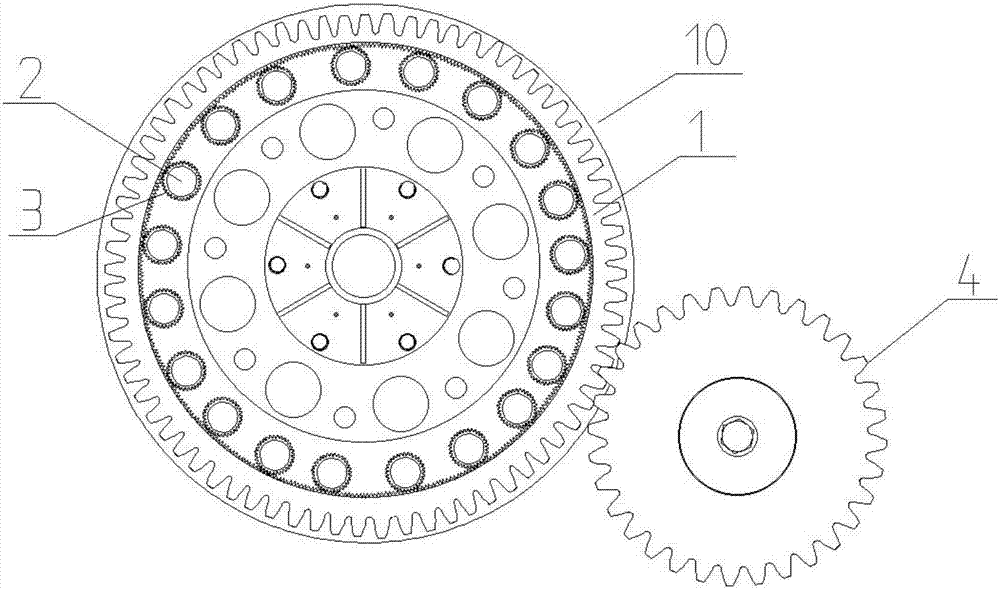
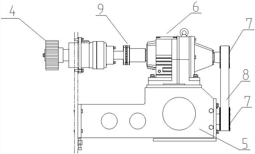
[0014] refer to Figure 1-2 , a driving mechanism for the raising roller of the raising machine, comprising a transmission ring gear 1, the transmission ring gear 1 is installed on the end of the main shaft of the raising machine cylinder 10, the transmission ring gear 1 is provided with internal teeth and external teeth, and the internal teeth Engaged transmission with the driven gear 3 that is fixed on the end of the raising roller 2; The driving mechanism of the raising roller also includes a servo motor 5 and a speed reducer 6 driven by the servo motor 5, and the servo motor 5 is connected with the synchronous pulley 7 and the synchronous belt 8 The power input end of the reducer 6 is connected, and the drive gear 4 is fixedly installed at the power output end of the red...


PUM


Abstract

The present invention relates to a driving mechanism for a raising roller of a raising machine, which comprises a transmission ring gear, which is installed on the end of the cylinder main shaft of the raising machine through a bearing. Engaged with the driven gear fixed at the end of the raising roller; the driving mechanism of the raising roller also includes a servo motor and a reducer driven by the servo motor, the servo motor is connected to the power input end of the reducer through a synchronous pulley and a synchronous belt, The drive gear is fixedly installed at the power output end of the reducer, and the drive gear is engaged with the external teeth of the transmission ring gear for transmission; the power input end of the reducer is equipped with an electromagnetic clutch; the present invention realizes that the raising roller rotates around the cylinder main shaft At the same time, it rotates around its own axis, and overcomes the disadvantages of unstable motor speed and belt slippage of the traditional raising roller drive mechanism, and has the advantages of stable driving speed and improved fabric raising quality.

Description

technical field [0001] The invention relates to a driving mechanism, in particular to a driving mechanism of a raising roller of a raising machine. Background technique [0002] During the operation of the raising machine, the raising machine cylinder drives the raising rollers that are evenly distributed in the circumference of the cylinder main shaft to rotate. At the same time, the raising rollers rotate around their own shafts. The driving mechanism of the raising rollers in the past usually uses three asynchronous motors as the driving mechanism. Drive power, because the speed of the three-phase asynchronous motor changes within a certain range, the load is different, the speed is not the same, there will be some speed difference, and the belt is prone to slipping, these factors lead to the extremely unstable running speed of the raising machine, Seriously affected the raising quality of fabric. Contents of the invention [0003] The technical problem to be solved by...

Claims


Application Information

Patent Timeline
IPC IPC(8): D06C11/00
CPCD06C11/00
Inventor 李婷
Owner 李婷
Learn More