

Automatic cloth clamping cutting mechanism
A cutting mechanism and clamping technology, which is applied in the cutting of textile materials, textiles and papermaking, etc., can solve the problems of affecting the effect of cloth winding, changing the tension of cloth, affecting the use, etc., and achieve the effect of improving the effect
- Summary
- Abstract
- Description
- Claims
- Application Information
AI Technical Summary
Problems solved by technology
Method used
Image

Examples
Embodiment Construction
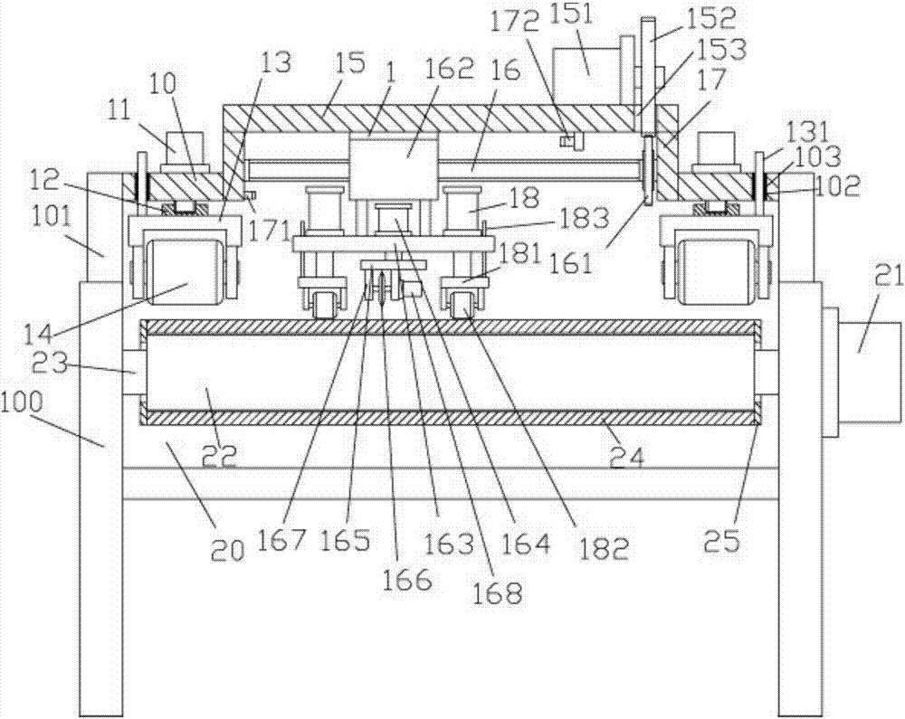
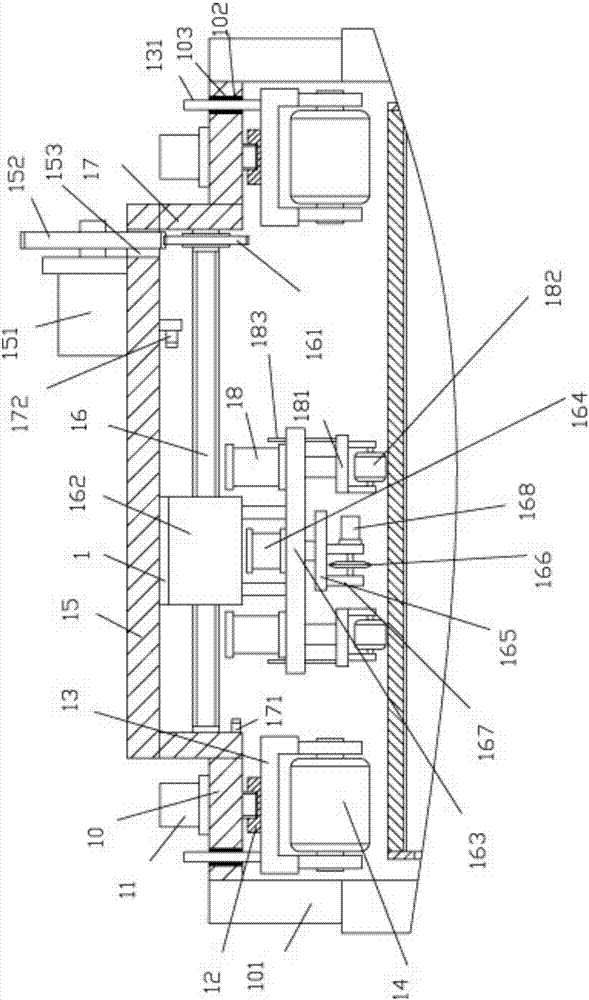
[0025] Examples, see e.g. Figure 1 to Figure 2 As shown, a cloth automatic clamping and cutting mechanism includes a frame 100, the upper part of the frame 100 is provided with a transmission roller 20, and the two ends of the transmission roller 20 are hinged on the two side support plates of the frame 100, wherein A drive motor 21 is fixed on the outer wall of a side support plate, the output shaft of the drive motor 21 is a spline shaft, and the spline shaft is inserted in the spline hole provided at one end of the drive roller 20, and the top surface of the side support plate is fixed There are upper supporting plates 101, and the two ends of the intermediate connecting beam 10 are fixed on the two upper supporting plates 101, and the top surfaces of both sides of the intermediate connecting beam 10 are fixed with side edge motors 11, and the output shafts of the side edge motors 11 pass through The middle connecting beam 10 is screwed with an adjusting sleeve 12, and the...
PUM
 Abstract
Description
Claims
Application Information