
Three-dimensional scanner frame

A scanner and frame technology, applied in the mechanical field, can solve the problems of cumbersome operation, low efficiency, and low efficiency of scanning measurement work, and achieve the effect of being suitable for popularization and application and improving the efficiency of scanning measurement

Inactive Publication Date: 2017-07-07
KUNMING UNIV
View PDF5 Cites 2 Cited by
  • Summary
  • Abstract
  • Description
  • Claims
  • Application Information

AI Technical Summary

Problems solved by technology

The adjustment of the camera position of the existing 3D scanners is mostly manually adjusted step by step to ensure that the fields of view of the two cameras overlap enough, the adjustment process is cumbersome and inefficient
Once the position of the camera changes, the camera must be calibrated, which makes the scanning measurement work inefficient

Method used


Image

  • Three-dimensional scanner frame
  • Three-dimensional scanner frame
  • Three-dimensional scanner frame

Examples


Embodiment Construction

[0010] The technical solutions of the present invention will be further described in detail below in conjunction with the accompanying drawings and specific embodiments.

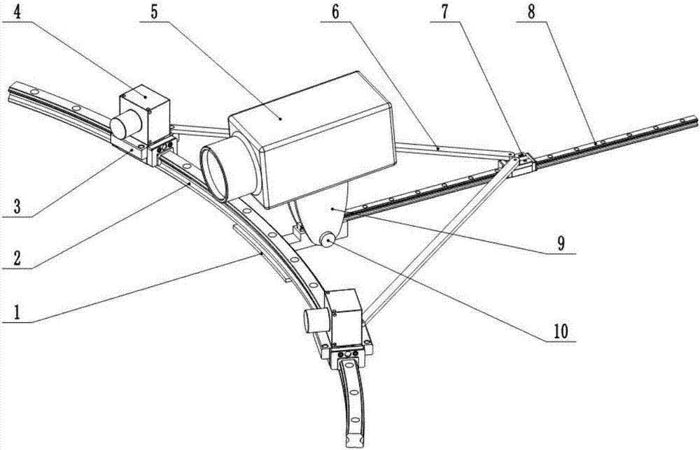
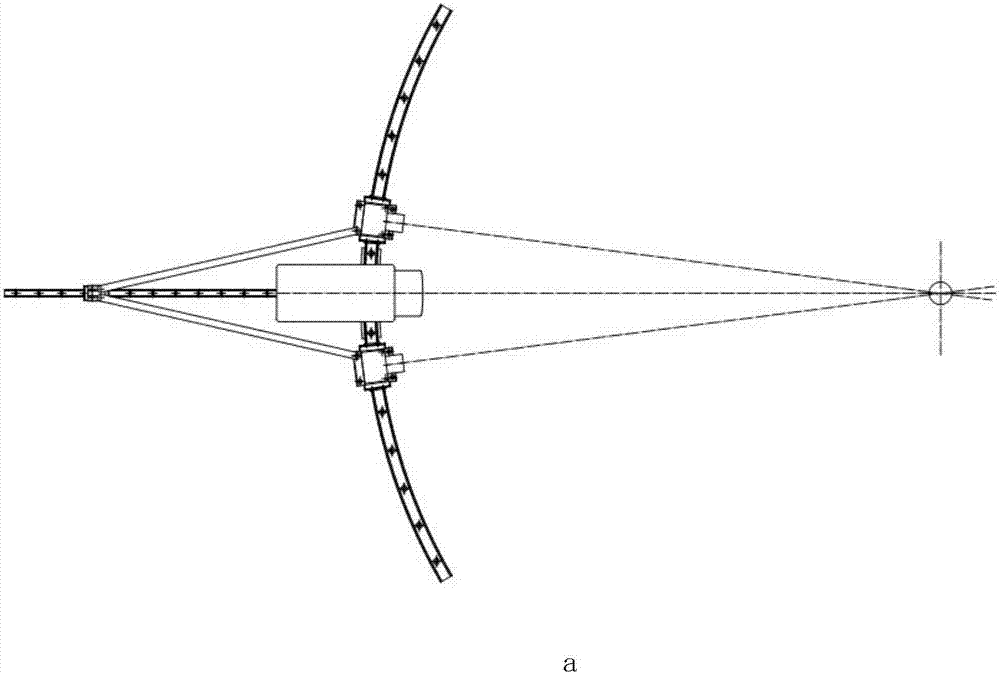
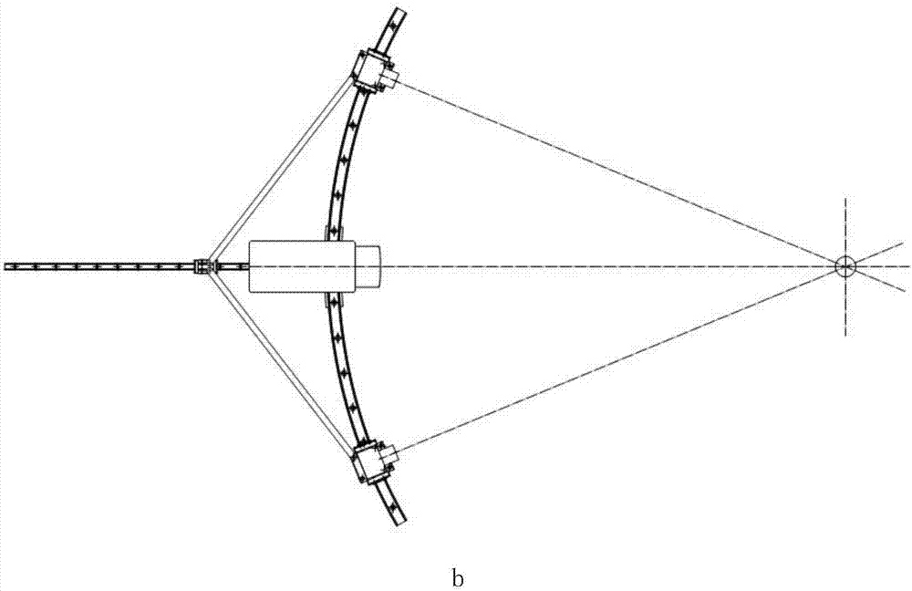
[0011] refer to figure 1 , a three-dimensional scanner frame, including a frame 1, an arc guide rail 2, an arc slide seat 3, a camera 4, a projector 5, a limit rod 6, a linear slide seat 7, a linear guide rail 8, and a projector mounting seat 9 and lock nut 10, arc guide rail 2 and linear guide rail 8 are installed on the frame 1, the direction of the linear guide rail 8 is the normal direction of arc guide rail 2; two arc slide seats 3 are installed on On the arc guide rail 2, it moves along the arc guide rail 2; the linear slide seat 7 is installed on the linear guide rail 8, and moves along the linear guide rail 8; two limit rods 6 respectively connect two arc slide seats 3 to the linear slide seat 7 , used to ensure that the positions of the two arc slides 3 are symmetrical with respect to the linear gu...


PUM


Abstract

The invention discloses a three-dimensional scanner frame, which comprises a frame, an arc guide rail, arc sliding seats, cameras, a projector, limiting rods, a linear sliding seat, a linear guide rail, a projector mounting seat and a locking nut, wherein the arc guide rail and the linear guide rail are arranged on the frame; the direction of the linear guide rail is the normal line direction of the arc guide rail; the two arc sliding seats are arranged on the arc guide rail and move along the arc guide rail; the linear sliding seat is arranged on the linear guide rail and moves along the linear guide rail; the two limiting rods are respectively connected with the two arc sliding seats to the linear sliding seat for ensuring the positions of the two arc sliding seats to be symmetrical relative to the linear guide rail; and the two cameras are arranged on the two arc sliding seats. According to the three-dimensional scanner frame disclosed by the invention, the view field centers of the two cameras are ensured to be constantly coincident during the camera position adjustment process, and when the device is used for three-dimensional scanning measurement, the scanning measurement efficiency can be effectively improved, and promotion and application are facilitated.

Description

technical field [0001] The invention belongs to the technical field of machinery and relates to a three-dimensional scanner frame. Background technique [0002] 3D scanning technology has been widely used in industry and service industries, such as 3D scanning detection and proofreading of the shape and size of parts, rapid 3D modeling of complex parts, 3D modeling of artworks and handmade products, and human body. Scan modeling and more. Although there are many ways to achieve three-dimensional imaging, the most widely used method is to use optical principles to measure the three-dimensional coordinates of the object surface. When the 3D scanner is in use, it is necessary to frequently adjust the position of the scanner camera to adapt to changes in the size and shape of the scanned object. The adjustment of the camera positions of the existing 3D scanners is mostly manually adjusted step by step to ensure that the fields of view of the two cameras are sufficiently overla...

Claims


Application Information

Patent Timeline
Patent Type & Authority Applications(China)
IPC IPC(8): G01B11/25G01B5/00
CPCG01B5/0004G01B11/2518
Inventor 安宇陈为民王玮
Owner KUNMING UNIV
Learn More