
Morphology scanning method and system

A scanning method and scanning system technology, applied in the field of three-dimensional shape scanning method and device, can solve problems such as traversal area limitation, achieve the effect of improving stability and reliability, and improving scanning measurement efficiency

Active Publication Date: 2020-05-19
BEIJING AEROSPACE INST FOR METROLOGY & MEASUREMENT TECH +1
View PDF9 Cites 0 Cited by
  • Summary
  • Abstract
  • Description
  • Claims
  • Application Information

AI Technical Summary

Problems solved by technology

Conventional area traversal is regular, such as circle, rectangle, square, triangle and other area traversal, but these traversal areas have certain restrictions, and in some special applications, the expected work tasks cannot be well completed

Method used


Image

  • Morphology scanning method and system
  • Morphology scanning method and system
  • Morphology scanning method and system

Examples


Embodiment 1

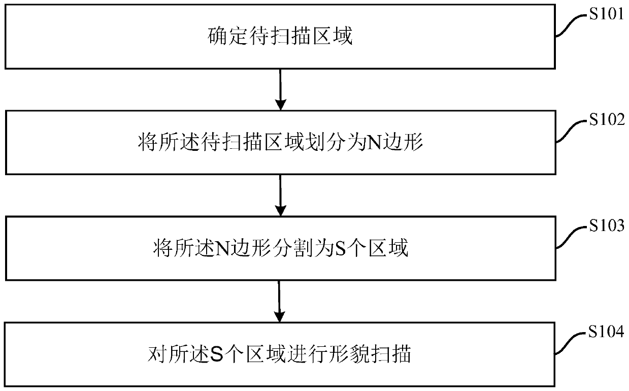
[0058] see figure 1 , is a schematic diagram of a topography scanning method provided in the embodiment of the present application. As shown in the figure, the method includes:

[0059] S101. Determine an area to be scanned.

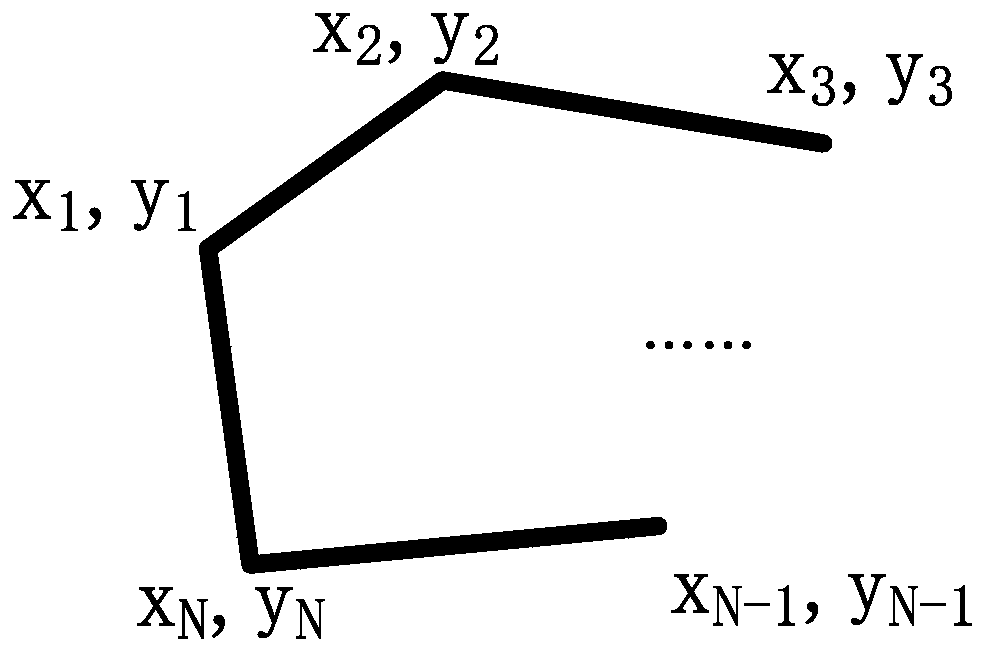
[0060] S102. Divide the area to be scanned into N polygons.

[0061] The N-gon can be an irregular N-gon defined by the user, which is determined according to the topographic features of the area to be scanned.

[0062] It should be noted that the N-gon is a convex N-gon, that is, any internal angle of the N-gon is less than 180 degrees. The size of N is determined by the shape of the area to be scanned and the scanning accuracy requirements, and N is greater than or equal to 3. Generally, the larger N is, the higher the scanning accuracy is.

[0063] Preferably, the area to be scanned is converted into mathematical coordinates first, and then the area to be scanned is divided into N polygons on the mathematical coordinates. Wherein, the origin of t...

Embodiment 2

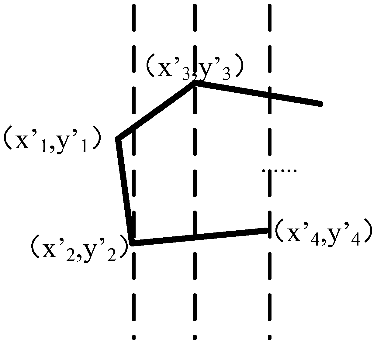
[0102] Such as Figure 8 As shown, this embodiment also provides a topography scanning method. For the cutting method of the segmented area, in addition to cutting along the direction of the ordinate, it can also cut along the direction of the abscissa. In order to achieve cutting along the abscissa direction, the original N-gon can be transformed as follows:

[0103] Step 1, with the origin as the center, the area to be scanned is rotated 90 degrees clockwise;

[0104] The second step is to determine the new mathematical coordinates x', y'. Wherein the origin of the new mathematical coordinates is the initial zero point of the scanning system, x'=-y, y'=x. x, y are the mathematical coordinates before rotation.

[0105] After transformation, on the x', y' coordinates, segment according to the same steps of S103, and scan according to the method of step S104, which will not be repeated in this embodiment.

[0106] Through the method of this embodiment, cutting and scanning...

Embodiment 3

[0108] Such as Figure 9 As shown, this embodiment also provides a topography scanning system, which is used to implement the method described in Embodiment 1 or Embodiment 2 above, and achieve the same effect as Embodiment 1 or Embodiment 2. This embodiment I won't go into details.


PUM


Abstract

The invention discloses a morphology method and a morphology device which are used for realizing complex region scanning, overcoming the restriction and limitation of single circular and rectangular region scanning on a scanning task, and completing user-defined irregular convex polygon region traversal. The method comprises the following steps: determining a region to be scanned; dividing the region to be scanned into N polygon; segmenting the N polygon into S segmentation regions; and performing morphology scanning on the S segmented regions. The embodiment of the invention further providesa morphology scanning device. According to the method of the embodiment, the region to be scanned is segmented, and then each segmented region is scanned, so that the problem of the scanning measurement of a three-dimensional topography measuring instrument on a complex area is solved, the scanning measurement efficiency is improved, and the stability and reliability are improved.

Description

technical field [0001] The present application relates to the field of detection, in particular to a three-dimensional shape scanning method and device. Background technique [0002] Area traversal refers to given the area to be scanned, then planning the path, and completing the traversal scan of the entire area in sequence. There are many implementation methods and approaches for region traversal, and different application scenarios have different requirements for traversing regions. Conventional area traversal is regular, such as area traversal of circles, rectangles, squares, triangles, etc., but these traversal areas have certain limitations, and in some special applications, the expected tasks cannot be well completed. Contents of the invention [0003] In view of the above technical problems, the embodiment of the present application provides a topography scanning method and device to realize complex area scanning, overcome the restrictions brought by single circul...

Claims


Application Information

Patent Timeline
Patent Type & Authority Applications(China)
IPC IPC(8): G01B11/24G06T7/11
CPCG01B11/24G06T2207/10004G06T7/11
Inventor 郭力振宋金城刘柯朱浩袁媛
Owner BEIJING AEROSPACE INST FOR METROLOGY & MEASUREMENT TECH
Learn More