
L-shaped tread mold

An L-shaped and mold technology, which is applied in the fields of mold shell/template/work frame, on-site preparation of building components, construction, etc., can solve the problems of high cost, inconvenient mold management, single mold specification, etc., and achieve cost saving, vibration reduction, etc. The effect of improving tamping efficiency and improving production efficiency

Pending Publication Date: 2017-07-11
XI'AN UNIVERSITY OF ARCHITECTURE AND TECHNOLOGY
View PDF6 Cites 1 Cited by
  • Summary
  • Abstract
  • Description
  • Claims
  • Application Information

AI Technical Summary

Problems solved by technology

[0004] At present, when pouring L-shaped steps, the mold specifications for pouring are single. Every time a L-shaped step is poured, a mold of the corresponding specification is required. Since there are many specifications of the steps, designing a mold for each specification is not only The cost is high, and it is not convenient to manage the mold, and the cost of storage, transportation and assembly of the mold is very high

Method used


Image

  • L-shaped tread mold
  • L-shaped tread mold
  • L-shaped tread mold

Examples


Embodiment Construction

[0040] The present invention will be further described below in conjunction with the accompanying drawings.

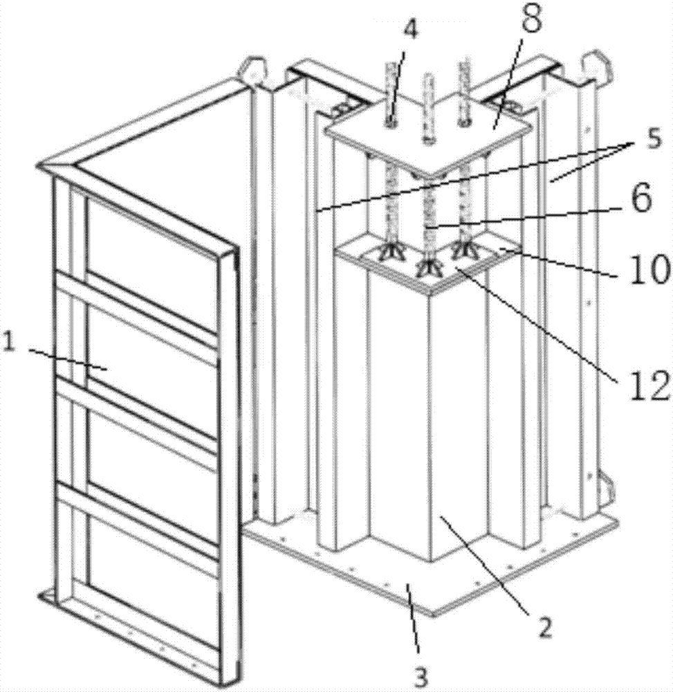
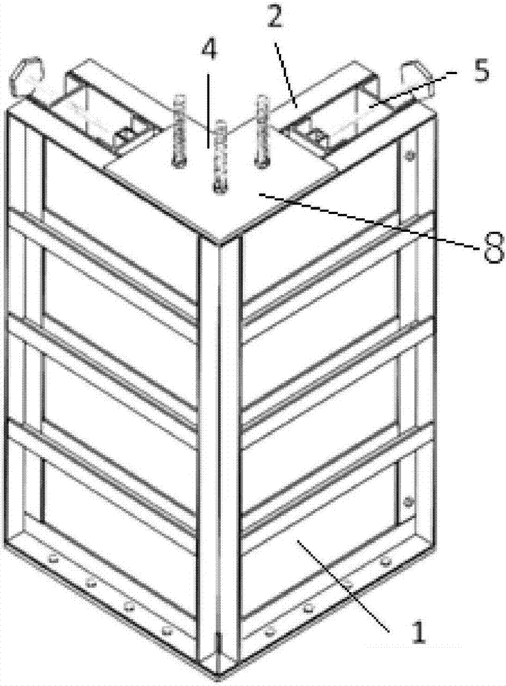
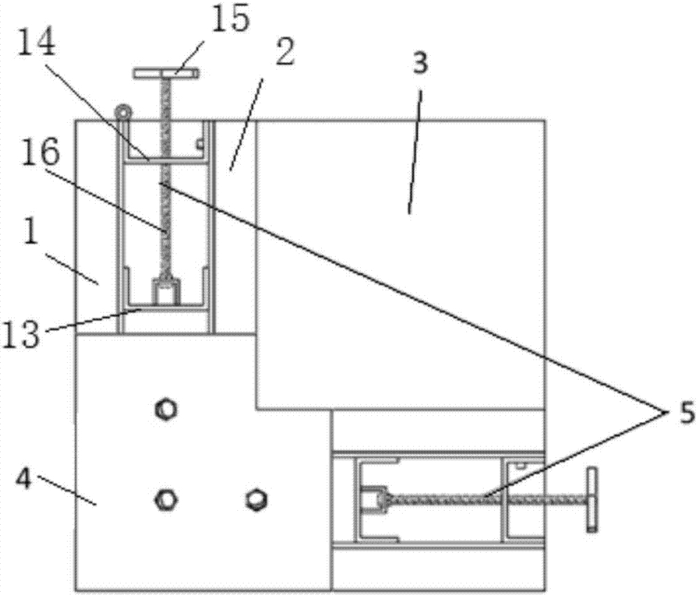
[0041] Such as Figure 1-Figure 6 As shown, the L-shaped stepping mold of the present invention comprises a horizontally arranged base plate 3, and the base plate 3 is fixedly connected with L-shaped clamping plate one 1 and clamping plate two 2. The inner surface of the clamping plate one 1 and the two clamping plates 2 is a plane, and Ribs are provided on the surface, the sides of clamping plate one 1 and clamping plate two 2 are perpendicular to base plate 3, and the corresponding sides of clamping plate one 1 and clamping plate two 2 are parallel, and the distance between clamping plate one 1 and clamping plate two 2 wallboards is the same as that to be The thickness of the processed L-shaped step is the same, and the thickness of the L-shaped step to be processed can be adjusted by adjusting the distance between the first splint 1 and the second splint 2, forming ...


PUM


Abstract

The invention belongs to the technical field of architectural devices, and particularly relates to an L-shaped tread mold. The L-shaped tread mold comprises a base plate arranged horizontally, a first L-shaped clamping plate and a second L-shaped clamping plate are arranged on the base plate, the distance between the first L-shaped clamping plate and a wall plate of the second L-shaped clamping plate is the same as the thickness of the L-shaped tread mold, a horizontal first pressing plate for restricting the height of the to-be-machined L-shaped tread mold is arranged on the upper portion of the space between the first L-shaped clamping plate and the second L-shaped clamping plate, a first driving device for restricting the height of the first pressing plate is arranged on the upper surface of the first pressing plate, and the lower portion of the first driving device is inserted into a cavity between the first L-shaped clamping plate and the second L-shaped clamping plate; second driving devices for restricting the side length the to-be-machined L-shaped tread mold are arranged in two lateral openings of the first L-shaped clamping plate and the second L-shaped clamping plate correspondingly, and the second driving devices are connected with the side edges of the first L-shaped clamping plate and the second L-shaped clamping plate; and an L-shaped cavity of the to-be-machined L-shaped tread mold is defined by the first L-shaped clamping plate, the second L-shaped clamping plate, the base plate, the first pressing plate and the two second driving devices, so that L-shaped tread of various specification can be machined through the L-shaped tread mold, cost is reduced, and production efficiency is improved.

Description

[0001] 【Technical field】 [0002] The invention belongs to the technical field of construction devices, and in particular relates to an L-shaped step mold. [0003] 【Background technique】 [0004] At present, when pouring L-shaped steps, the mold specifications for pouring are single. Every time a L-shaped step is poured, a mold of the corresponding specification is required. Since there are many specifications of the steps, designing a mold for each specification is not only The cost is high, and it is inconvenient to manage the mould, and the cost of storage, transportation and assembly of the mould is very high. [0005] 【Content of invention】 [0006] In order to solve the problems existing in the prior art, the object of the present invention is to provide an L-shaped step mold, which can be used to process L-shaped steps of various specifications, thereby saving costs and improving production efficiency. [0007] The purpose of the present invention is achieved through ...

Claims


Application Information

Patent Timeline
IPC IPC(8): E04G13/06
CPCE04G13/062
Inventor 郝际平何梦楠赵子健孙晓岭薛强樊春雷张峻铭黄育琪刘斌陈永昌刘瀚超
Owner XI'AN UNIVERSITY OF ARCHITECTURE AND TECHNOLOGY
Learn More