
OLED display and manufacturing method thereof
A manufacturing method and display technology, which are applied in semiconductor/solid-state device manufacturing, electrical components, electrical solid-state devices, etc., can solve the problem of OLED display screen being difficult to truly achieve integrated black production costs, and achieve soft, non-dazzling light and impact resistance. Unaffected strength, avoids dazzling effects
- Summary
- Abstract
- Description
- Claims
- Application Information
AI Technical Summary
Problems solved by technology
Method used
Image

Examples
Embodiment 1
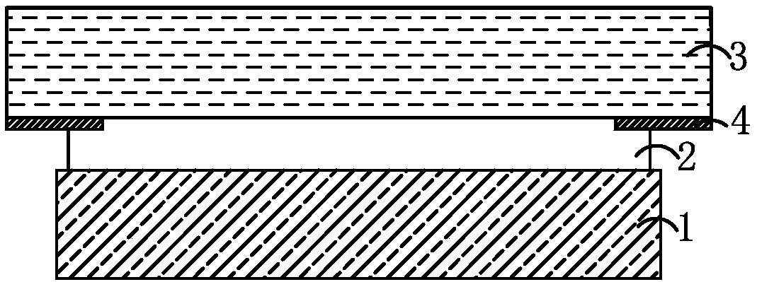
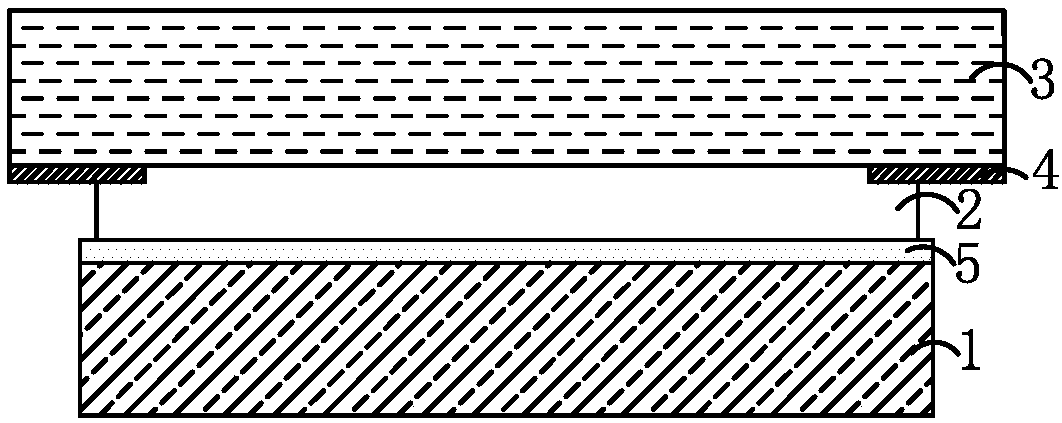
[0039] This embodiment provides an OLED display, such as figure 1 As shown, the OLED display screen includes a display module 1, an optical adhesive 2 and a cover glass 3 arranged in sequence from bottom to top, and the transmittance of the cover glass 3 to visible light is 65%. The optical glue 2 is a full lamination glue, and the optical glue 2 sticks the cover glass 3 on the display module 1 through a full lamination process.
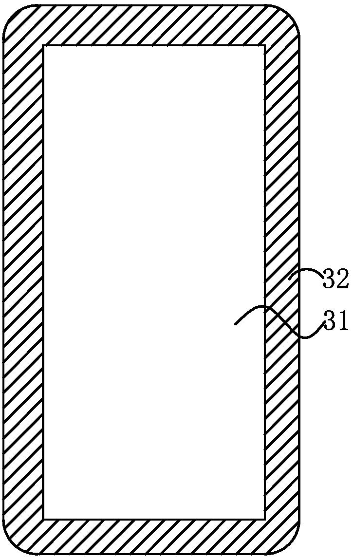
[0040] which, combined with figure 2 As shown, the cover glass 3 includes a visible area 31 located in the middle and a non-visible area 32 located around the periphery. A black ink layer is printed on the lower surface of the non-visible area 32 to form a black frame 4. The cover glass 3 is printed with The lower surface of the black frame 4 is opposite to the display module 1 . The display module 1 of this embodiment may be a display module in the prior art, and the display module 1 may only have a display function, or may have both display and ...
Embodiment 2
[0050] The difference between the present embodiment and the first embodiment is that the light transmittance of the cover glass in the present embodiment to visible light is 55%.
Embodiment 3
[0052] The difference between the present embodiment and the first embodiment is that the light transmittance of the cover glass in the present embodiment to visible light is 50%.
PUM
 Abstract
Description
Claims
Application Information