Device and method for angular transformation imaging

A technology for transforming and transforming equations, which is applied in the field of angle transformation imaging methods and devices, can solve the problem that the ellipse expansion imaging method is no longer suitable, and achieves the effect of eliminating the problem of unsatisfactory focusing imaging, improving imaging effects, and improving imaging accuracy.

Active Publication Date: 2017-07-14
恒泰艾普集团股份有限公司
View PDF4 Cites 7 Cited by
  • Summary
  • Abstract
  • Description
  • Claims
  • Application Information

AI Technical Summary

Problems solved by technology

Under the condition of inhomogeneous media, there is a difference between the speed of upgoing waves and the speed of downg

Method used


Image

  • Device and method for angular transformation imaging
  • Device and method for angular transformation imaging
  • Device and method for angular transformation imaging

Examples


Embodiment Construction

[0043] Embodiments of the present invention are described in detail below, examples of which are shown in the drawings, wherein the same or similar reference numerals designate the same or similar elements or elements having the same or similar functions throughout. The embodiments described below by referring to the figures are exemplary and are intended to explain the present invention and should not be construed as limiting the present invention.

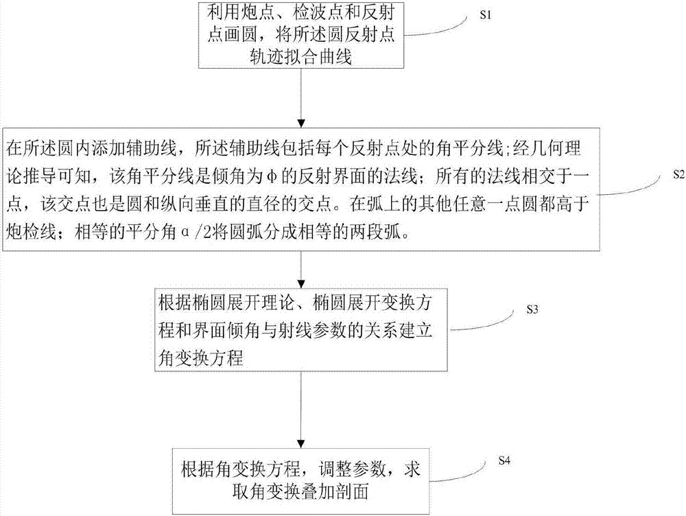
[0044] Such as figure 1 As shown, the embodiment of the present invention proposes an angle transformation imaging method, comprising the following steps:

[0045] Step S1, using shot points, receiver points and reflection points to draw a circle, and fitting the trajectory of the circle reflection points to a curve.

[0046] Step S2, adding an auxiliary line in the circle, the auxiliary line includes the bisector of the angle at each reflection point, and it can be known from the derivation of the geometric theory that the bise...


PUM


Abstract

The invention provides a device and a method for angular transformation imaging. Specifically, seismic stack imaging is realized by scanning two parameters, namely, the included angle between downward wave and upward wave and the formation dip. The problem that focused imaging is unsatisfactory due to the fact that the actual seismic wave ray velocity is different from the normal imaging velocity estimated using an elliptic expansion method is eliminated. The imaging effect is improved, and the imaging accuracy is increased. Better and more basic data is provided for subsequent processing.

Description

technical field [0001] The invention relates to the technical field of reflection seismic data processing in seismic exploration, in particular to an angle transformation imaging method and device. Background technique [0002] With the continuous development of seismic exploration, in the actual seismic data processing and production, the method of conventional common center point (CMP) trace set motion correction (NMO) and post-stacking is mainly used. It assumes that the underground is a horizontally layered uniform medium, and uses CMP extraction, hyperbolic dynamic correction, and multiple coverage in-phase stacking methods to achieve stacked imaging. When the underground structure is relatively simple and the stratum dip angle is small, a relatively good stacking section can be obtained. However, when the formation is inclined or curved, the reflection points diverge, and it is difficult for this method to realize the in-phase superposition of the common reflection po...

Claims


Application Information

Patent Timeline
IPC IPC(8): G01V1/28G01V1/34
CPCG01V1/28G01V1/345G01V2210/74
Inventor 周青春谢桂生康德拉什科夫姜瑞友陈相君田迎春张云波
Owner 恒泰艾普集团股份有限公司
Why Eureka
Try Eureka