Charge sharing calibration method and system

Active Publication Date: 2021-03-04
KONINKLJIJKE PHILIPS NV
View PDF0 Cites 0 Cited by
  • Summary
  • Abstract
  • Description
  • Claims
  • Application Information

AI Technical Summary

Benefits of technology

[0006]There may be a need for alternative w

Problems solved by technology

An undesirable phenomenon of “charge sharing” may occur in these type of detector or similar event counters.
“Charge sharing” is an effect where the ver

Method used


Image

  • Charge sharing calibration method and system
  • Charge sharing calibration method and system
  • Charge sharing calibration method and system

Examples


Example

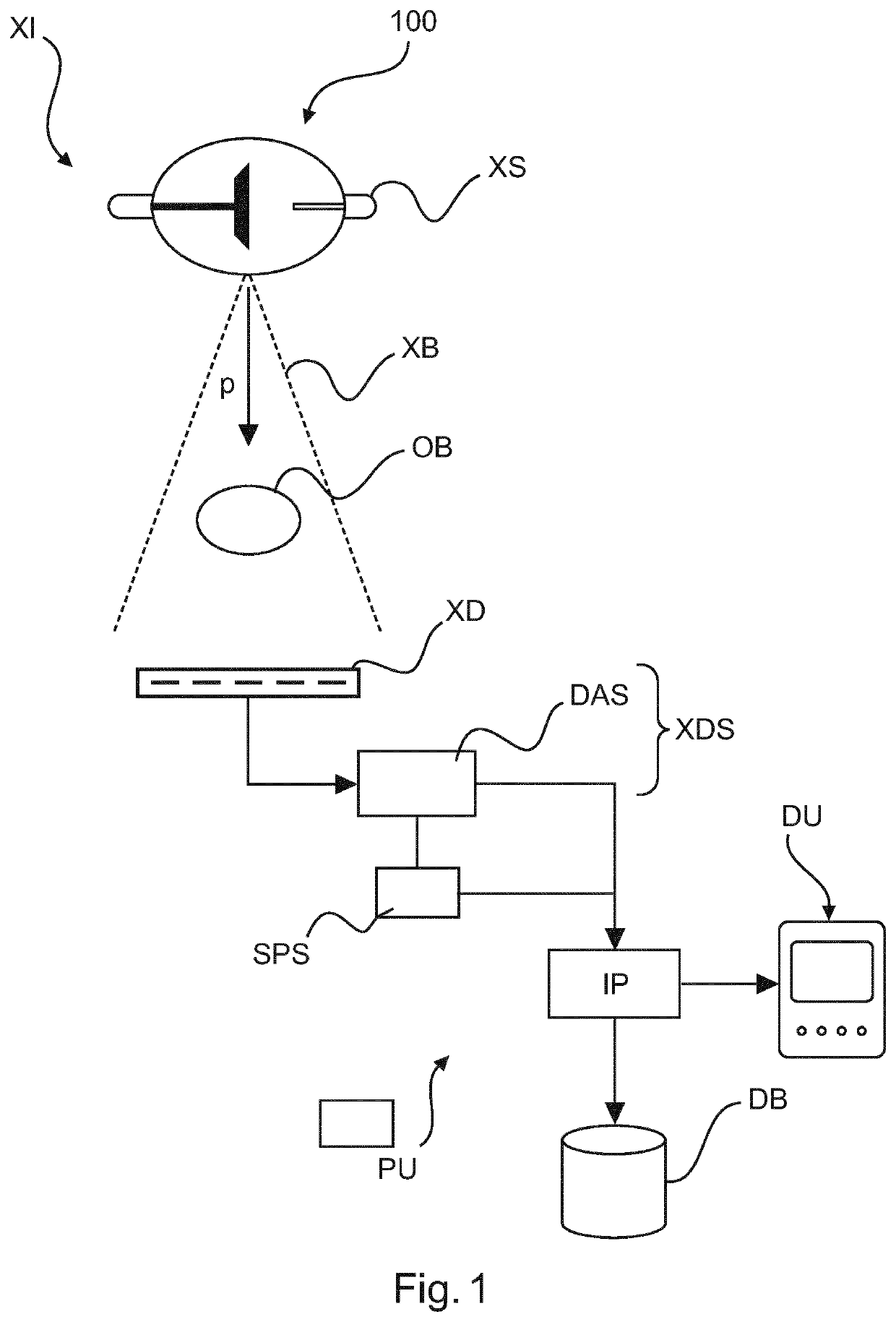
[0038]With reference to FIG. 1, there is shown a schematic block diagram of an X-ray imaging arrangement 100 including an X-ray imaging apparatus XI (also referred to herein as the “imager”), such as a Computed Tomography apparatus, projection radiography, etc.

[0039]The imager XI is configured to produce imagery, in particular in relation to an internal structure and / or material composition of an object OB. The object OB may be animate or inanimate. In particular, the object is a human or animal patient or a part thereof.

[0040]The X-ray imager XI is particularly envisaged for, preferably, spectral or photon counting (energy resolving) imaging in the medical field but other applications in non-medical fields are not excluded herein, such as baggage scanning or non-destructive material testing (NDT), etc.

[0041]The X-ray imaging apparatus XI includes an X-ray source XS configured to emit X-radiation.

[0042]At a distance from the X-ray source XS, across an examination region, there is ar...


PUM


Abstract

A signal processing system (SPS) and related method. The system comprises an input interface (IN) for receiving at least two data sets, comprising a first data set and second data set. The first data set is generated by an X-ray detector sub-system (XDS) at a first pixel size and the second data set generated at a second pixel size different from the first pixel size. An estimator (EST) is configured to compute, based on the two data sets, an estimate of a charge sharing impact.

Description

FIELD OF THE INVENTION[0001]The invention relates to a signal processing system, to a signal processing method, to an imaging arrangement, to a computer program element and to a computer readable medium.BACKGROUND OF THE INVENTION[0002]Some X-ray imaging apparatuses, such as computed tomography (CT) scanners, radiography apparatuses or others, use energy discriminating detector equipment. Unlike more traditional detectors that are merely energy integrating, energy discriminating detector systems are capable to analyze the energy spectrum of the X-radiation. This additional information extraction allows for instance spectral imaging to learn about the material composition of the imaged sample.[0003]One type of such energy discriminating detector systems are direct conversion photon counting detectors. These use largely unstructured semiconductors for conversion of X-radiation into detector signals. Structuring or “pixilation” is achieved by arranging a plurality of electrodes on the ...

Claims


Application Information

Patent Timeline
IPC IPC(8): H04N5/32A61B6/00G01N23/046
CPCH04N5/32G01N23/046A61B6/482G01T1/17G01T1/2928
Inventor STEADMAN BOOKER, ROGERROESSL, EWALD
Owner KONINKLJIJKE PHILIPS NV
Why Eureka
Try Eureka