image forming device

An image and image carrier technology, which is applied to the electric recording process applying charge patterns, equipment and instruments of the electric recording process applying charge patterns, etc., can solve the problems of paper jams in the intermediate transfer unit, and achieve the effect of suppressing paper jams

Active Publication Date: 2020-01-07
KYOCERA DOCUMENT SOLUTIONS INC
View PDF10 Cites 0 Cited by
  • Summary
  • Abstract
  • Description
  • Claims
  • Application Information

AI Technical Summary

Problems solved by technology

[0003] However, in the above conventional image forming apparatus, there is a problem that the paper that has passed through the secondary transfer nip may enter the intermediate transfer unit without being separated from the intermediate transfer belt due to the action of electricity or the surrounding environment. between the fuser unit and the fuser unit, causing a paper jam in the intermediate transfer unit
Especially, in the case of using thin paper or paper containing a lot of moisture, this disadvantage is easy to occur
In addition, if paper enters between the intermediate transfer unit and the fixing unit, in order to remove the paper, it is necessary to remove the intermediate transfer unit from the main body of the device, which is a complicated work, so a technical service person is required to deal with it.

Method used


Image

  • image forming device
  • image forming device
  • image forming device

Examples


no. 1 approach

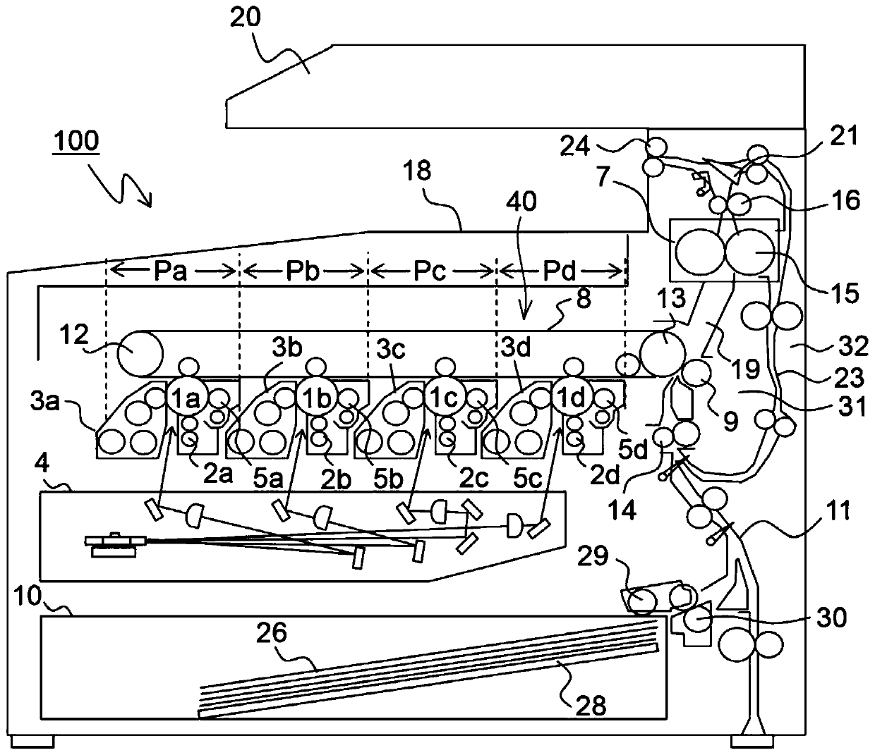
[0024] refer to Figure 1 to Figure 6 The image forming apparatus 100 according to the first embodiment of the present invention will be described. Such as figure 1 As shown, the image forming apparatus 100 is a tandem color copier, and inside the main body of the image forming apparatus 100 there are figure 1 Four image forming sections Pa, Pb, Pc, and Pd are arranged in this order from the left side. Corresponding to images of four different colors (yellow, magenta, cyan, and black), image forming parts Pa to Pd are provided respectively, and yellow, magenta, cyan, and Cyan and black images.

[0025] Photosensitive drums (image carriers) 1a, 1b, 1c, and 1d carrying visible images (toner images) of various colors are arranged in these image forming portions Pa to Pd, respectively. figure 1 Among them, an endless intermediate transfer belt 8 rotating in the counterclockwise direction is provided adjacent to each of the image forming sections Pa to Pd. The toner images for...

no. 2 approach

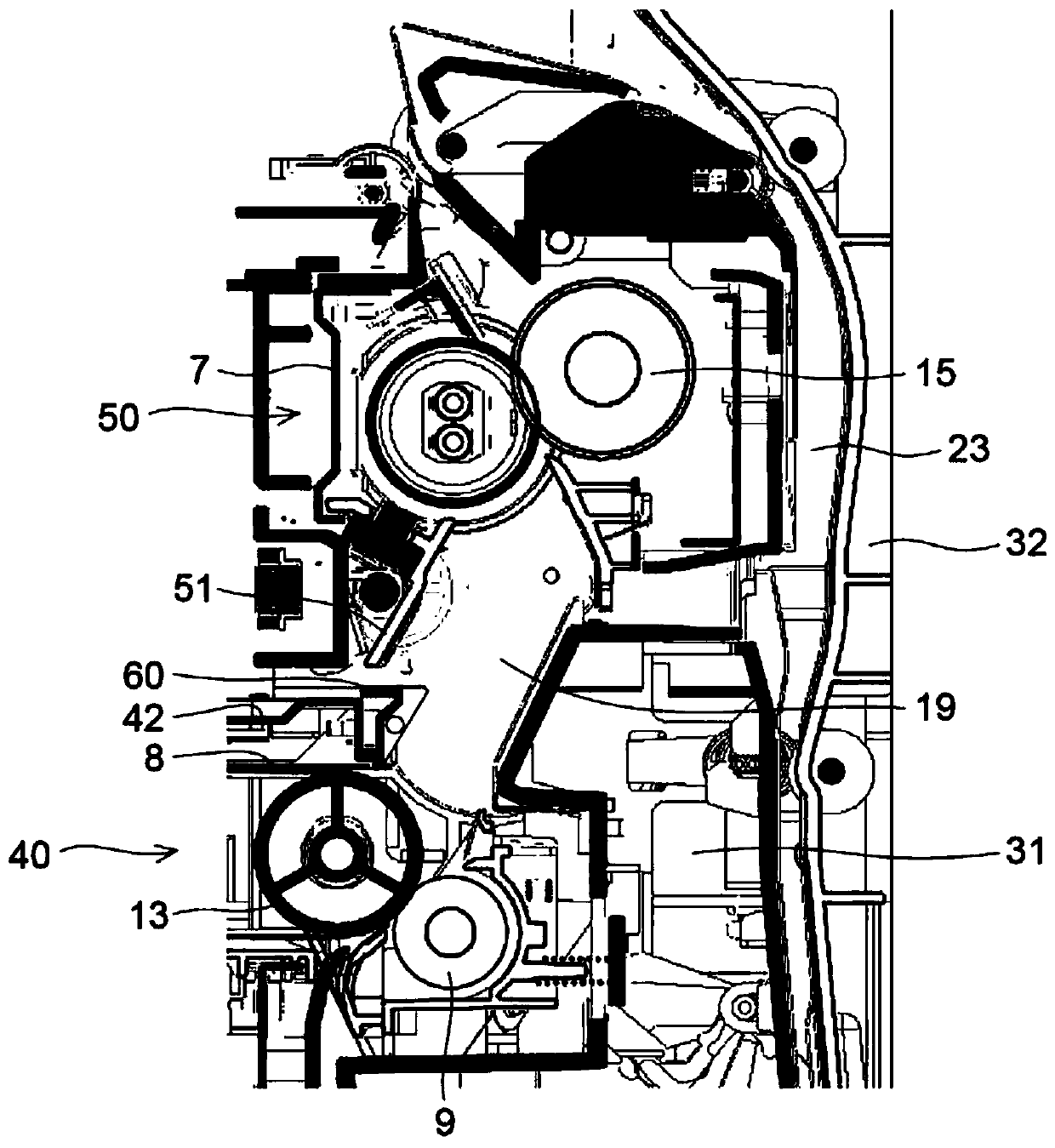
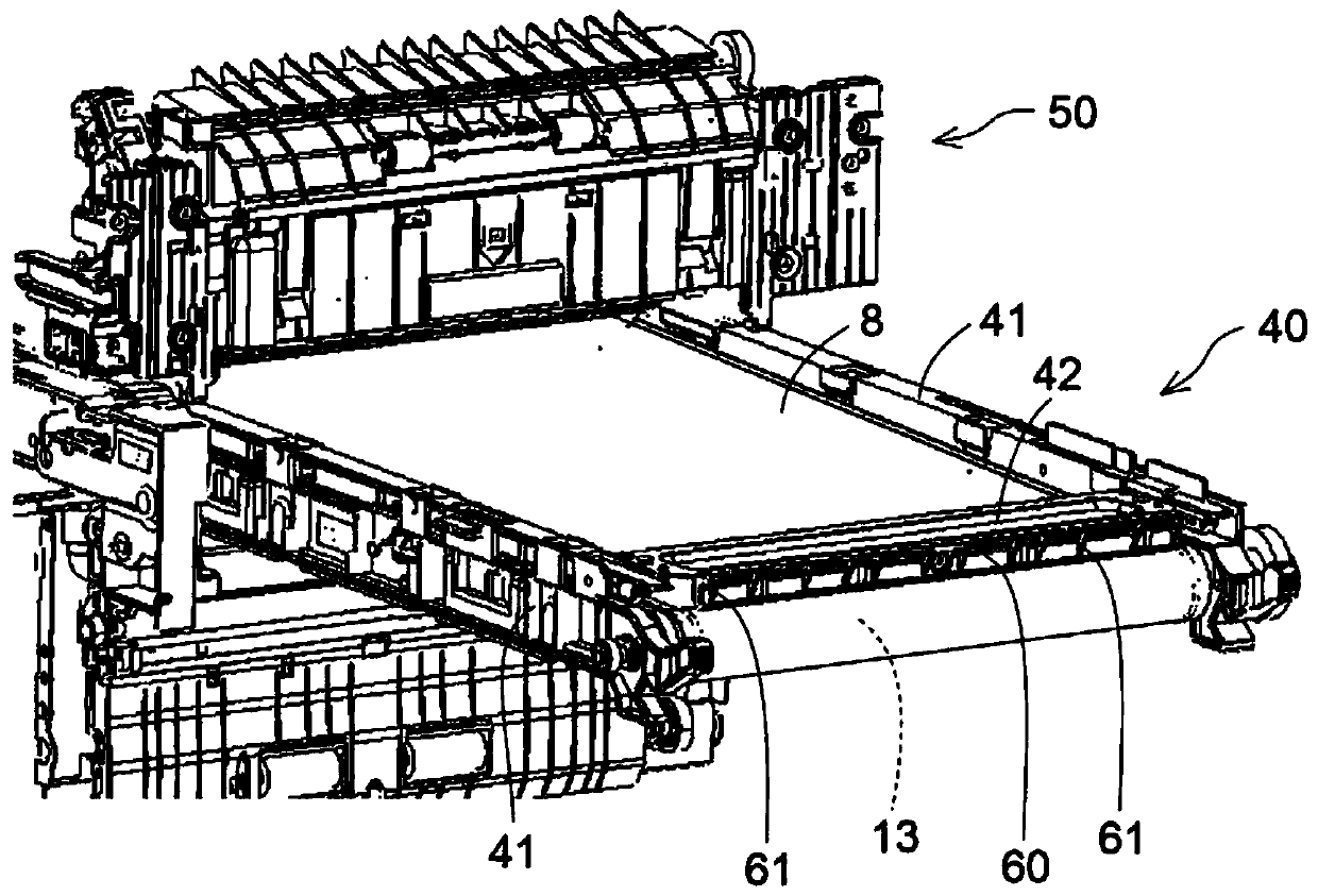
[0054] Such as Figure 7 As shown, in the image forming apparatus 100 of the second embodiment of the present invention, as in the first embodiment, the entry suppressing member 60 is provided on the intermediate transfer unit 40 .

[0055] In addition to a plurality of guide ribs 61 that guide the paper 26 toward the fixing nip (fixing portion), the entry suppressing member 60 has a swing shaft 62 disposed near the lower end. Such as Figure 7 as well as Figure 8 As shown, the entry inhibiting member 60 is capable of swinging about a swing shaft 62 .

[0056] In the second embodiment, a solenoid (drive unit) 70 for swinging (driving) the entry suppression member 60 is provided on the device main body. In addition, by a compression coil spring (biasing member) not shown in the figure, the entry restraining member 60 is biased toward the standing direction ( Figure 7 counterclockwise) force.

[0057] The solenoid 70 includes a main body portion 70a and a plunger 70b that...

no. 3 approach

[0066] In the image forming apparatus 100 of the third embodiment of the present invention, as Figure 9 As shown, unlike the first embodiment and the second embodiment, the entry suppressing member 60 is provided on the fixing unit 50 .

[0067] In addition to a plurality of guide ribs 61 that guide the paper 26 toward the fixing nip (fixing portion), the entry suppressing member 60 has a swing shaft 62 disposed near the upper end. Such as Figure 9 as well as Figure 10 As shown, the entry inhibiting member 60 is capable of swinging about a swing shaft 62 . In addition, the direction in which the lower end portion of the entry suppression member 60 approaches the intermediate transfer belt 8 is applied to the entry suppression member 60 by a compression coil spring (urging member) not shown in the figure ( Figure 9 clockwise) force.

[0068] When the solenoid 70 becomes ON, as Figure 9 As shown, the plunger 70b is disposed at the retracted position, and the lower end ...


PUM


Abstract

An image forming apparatus of the present disclosure includes an image carrier, an intermediate transfer unit, a secondary transfer roller, and a fixing unit. The intermediate transfer unit includes an intermediate transfer belt, and a driving and driven rollers that rotatably stretch the intermediate transfer belt, and the intermediate transfer unit is insertable / drawable with respect to an apparatus main body. The secondary transfer roller and the intermediate transfer belt constitute a nip portion. The fixing unit is disposed above the intermediate transfer unit, and fixes a toner image on a recording medium. The intermediate transfer unit includes an entry restriction member that restricts entry of a recording medium into a space between the intermediate transfer unit and the fixing unit.

Description

technical field [0001] The present invention relates to an image forming apparatus, and more particularly, to an image forming apparatus including an intermediate transfer unit having an intermediate transfer belt and a fixing unit disposed above the intermediate transfer unit. Background technique [0002] Conventionally, a color image forming apparatus including an intermediate transfer belt for transferring toner images formed on a plurality of photosensitive drums (image carriers) is known. A color image forming apparatus includes, for example: a plurality of photosensitive drums; an intermediate transfer unit including an intermediate transfer belt, and a driving roller and a driven roller rotatably tensioning the intermediate transfer belt; a second transfer roller, and The intermediate transfer belt constitutes a secondary transfer nip; and a fixing unit, disposed above the intermediate transfer unit, fixes the toner image transferred from the intermediate transfer be...

Claims


Application Information

Patent Timeline
Patent Type & Authority Patents(China)
IPC IPC(8): G03G15/14G03G21/16
CPCG03G15/14G03G21/168G03G15/1605G03G15/657G03G2215/0132
Inventor 大西祥太
Owner KYOCERA DOCUMENT SOLUTIONS INC
Why Eureka
Try Eureka