Paper supply device, automatic paper transferring device and image formation device

A paper feeding device and paper technology, which are applied in the directions of object supply, transportation and packaging, and object separation, etc., can solve the problems of bending and folds, paper jams, large angles, etc., and achieve the effects of suppressing deformation, suppressing paper jams, and reducing paper jams

Inactive Publication Date: 2018-10-09
KONICA MINOLTA TECH DEV WUXI
View PDF5 Cites 0 Cited by
  • Summary
  • Abstract
  • Description
  • Claims
  • Application Information

AI Technical Summary

Problems solved by technology

like Image 6 As shown, the distance between the pick-up roller 20 and the separation roller 40 is relatively long, and the angle is relatively large. At this time, the paper P, especially the thin paper, is likely to be bent, wrinkled and jammed during the conveying process.

Method used


Image

  • Paper supply device, automatic paper transferring device and image formation device
  • Paper supply device, automatic paper transferring device and image formation device
  • Paper supply device, automatic paper transferring device and image formation device

Examples


Embodiment approach 1

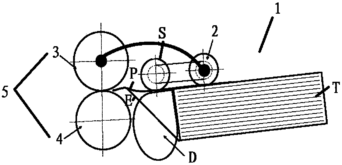
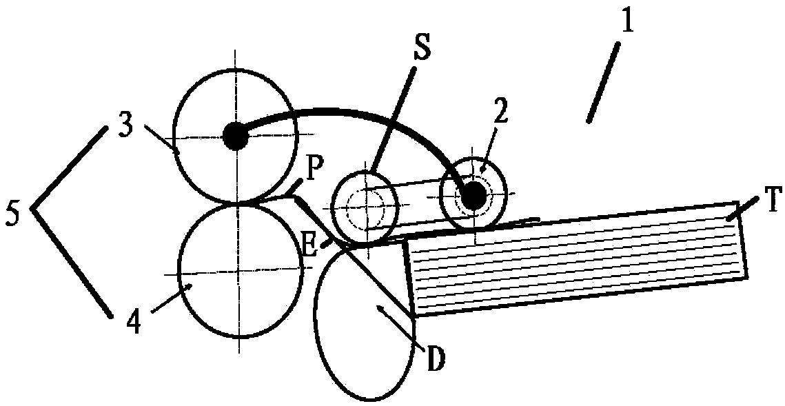
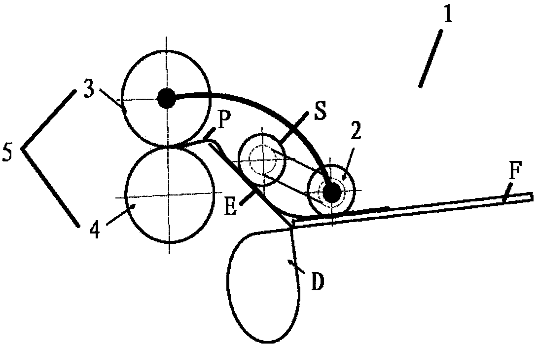
[0035] Fig. 1 (A), Fig. 1 (B), Fig. 1 (C) are the schematic diagrams of the paper feeding device of Embodiment 1 of the present invention, wherein, Fig. 1 (A) shows the state when paper is fully loaded, and Fig. 1 (B ) shows the state when the paper is half-loaded, and FIG. 1(C) shows the state when the paper is empty.

[0036]As shown in FIG. 1(A), the paper feeding device 1 according to Embodiment 1 of the present invention is mainly composed of the following parts: a paper feeding tray F on which a paper stack T is placed; a paper pickup roller 2, It extracts the paper P from the paper stack T and conveys it to the paper feed roller pair 5; The nip between the separation rollers 4, through which paper is fed one by one to the image forming device; Between the rollers 4), when the paper P is conveyed, the paper is supported from the lower side of the paper P, and the position is changed according to the height of the paper stack T, that is, the decrease or increase of paper...

Embodiment approach 2

[0056] Fig. 3 (A), Fig. 3 (B) and Fig. 3 (C) are the schematic diagrams of the paper feeding device of embodiment 2 of the present invention, wherein, Fig. 3 (A) shows the state when paper is fully loaded, Fig. 3 (B ) shows the state when the paper is half-loaded, and FIG. 3(C) shows the state when the paper is empty.

[0057] In this embodiment, only the auxiliary mechanism is different from Embodiment 1, and other configurations are the same as Embodiment 1. Here, the same reference numerals as in Embodiment 1 are given to the same parts as in Embodiment 1, and description thereof will be omitted.

[0058] Such as Figure 3(A)-Figure 3(C) As shown, the auxiliary mechanism in Embodiment 2 is the belt S1. The belt S1 wraps around the pick-up roller 2 and the linkage roller 6, and has a certain width. During the paper conveying process, the pick-up roller 2 rotates, and the belt S1 rotates accordingly, and the conveying force is generated by the contact between the belt S1 an...

Embodiment approach 3

[0063] 4(A), FIG. 4(B) and FIG. 4(C) are schematic diagrams of the paper feeding device according to Embodiment 3 of the present invention, wherein FIG. 4(A) shows the state when the paper is fully loaded, and FIG. 4(B ) shows the state when the paper is half-loaded, and FIG. 4(C) shows the state when the paper is empty.

[0064] In this embodiment, only the auxiliary mechanism is different from Embodiment 1, and other configurations are the same as Embodiment 1. Here, the same reference numerals as in Embodiment 1 are given to the same parts as in Embodiment 1, and description thereof will be omitted.

[0065] Such as Figure 4(A)-Figure 4(C) As shown, the auxiliary mechanism in Embodiment 3 is paddle S2. This paddle S2 is constituted by a cylindrical member 7 as a main body and a plurality of paddle pieces 8 protruding from the surface of the cylindrical member 7 in a direction tangential to the outer circumference of the cylindrical member 7 . The central shaft portion o...


PUM


Abstract

The invention provides a paper supply device, an automatic paper transferring device and an image formation device. By adoption of the paper supply device, the automatic paper transferring device andthe image formation device, when a large quantity of paper is supplied, and deformation of the paper can be reduced during paper transferring to make sure that different types of paper can be smoothlytransferred to a clamping part of a separation roller. The paper supply device (1) is provided with a paper fetching roller (2), a paper supply roller pair (5) and a movable guide block (D), whereinthe paper fetching roller (2) fetches paper from a paper stack (T) and transfers the paper to the paper supply roller pair (5); the paper supply roller pair (D) is used for supplying the paper transferred from the paper fetching roller (2) to the image formation device piece by piece; and the movable guide block (D) is located between the paper fetching roller (2) and the paper supply roller pair(5) and is used for supporting the paper from the lower side of the paper when the paper is transferred, and the position of the movable guide block (D) can be changed according to the height of the paper stack (T). The paper supply device (1) is further provided with an auxiliary mechanism (S). The auxiliary mechanism is located between the paper fetching roller (2) and the paper supply roller pair (5) and is used for assisting in paper transferring from the upper side of the paper when the paper is transferred.

Description

technical field [0001] The present invention relates to a paper feeding device, and more particularly to a paper feeding device corresponding to large-capacity paper feeding, an automatic paper conveying device and an image forming apparatus provided with the paper feeding device. Background technique [0002] For a general paper feeding device, when corresponding to a stack of paper, the paper feeding and feeding can be performed by lowering the paper pick-up roller. However, in this paper feeding device, as the number of paper sheets in the paper stack increases, the gap between the front end of the uppermost paper in the paper stack and the pair of paper feed rollers increases. , because there is no guide rail between the rollers, and the space is large, the paper is easily bent and deformed due to the weight of the paper during the conveyance process after the paper is picked up by the pick-up roller and transported to the paper-feed roller pair, and the paper may be sep...

Claims


Application Information

Patent Timeline
Patent Type & Authority Applications(China)
IPC IPC(8): B65H3/06B65H3/66B65H5/06
CPCB65H3/0669B65H3/66B65H5/062B65H2701/1131B65H2801/03
Inventor 高磊
Owner KONICA MINOLTA TECH DEV WUXI
Why Eureka
Try Eureka