A remote two-way optical phase comparison method and device based on local measurement

An optical phase, local end technology, applied in optics, optical components, two-way transmission, etc., can solve the problems of high time synchronization requirements, influence comparison results, complex circuit devices, etc., to achieve a simplified experimental scheme, simple RF devices, Wide Bandwidth Effect

Active Publication Date: 2019-07-26
NAT TIME SERVICE CENT CHINESE ACAD OF SCI
View PDF1 Cites 0 Cited by
  • Summary
  • Abstract
  • Description
  • Claims
  • Application Information

AI Technical Summary

Problems solved by technology

[0005] 1. The existing technology schemes have high requirements on the time synchronization of the phase measurement process in different places. It is necessary to ensure that the acquisition of the phase or frequency information of the beat frequency signals in the two places has a high degree of simultaneity, and it is not easy to realize the true sense of different places.
[0006] 2. Some components of the circuit required by the existing technology scheme are relatively complex, and it is easy to introduce irrelevant radio frequency noise, which affects the comparison result

Method used


Image

  • A remote two-way optical phase comparison method and device based on local measurement

Examples


Embodiment Construction

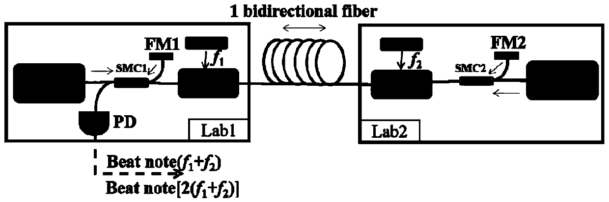
[0031] The two-way optical phase comparison method based on the measurement of the local end of the present invention uses two lasers separated from the two places as light sources, and is connected with a long-distance optical fiber link, and the output optical signals of the two lasers propagate in opposite directions on the same optical fiber at the same time , the signal light of one of the lasers is sent to the local end Lab1 through the optical fiber link and beats with the other laser. By comparing the phase of the two beat frequency signals, the common-mode phase noise of the fiber link is passively eliminated, so as to realize the comparison of the two lasers.

[0032] In order to realize the above method, the present invention proposes a device such as figure 1 Shown: including optical structure and electrical part; optical structure is composed of local end optical path part, optical fiber link part and remote optical path part; electrical part is composed of detect...


PUM


Abstract

The invention discloses a remote bidirectional optical phase comparison method based on local end measurement and a realization device thereof. Two lasers separated at two different places are taken as light sources. The two lasers are connected through a remote optical fiber link. Output light signals of the two lasers are transmitted on the same optical fiber in opposite directions. The signal light of one laser is sent to the local end through the optical fiber link and carries out frequency beat with the other laser. The signal light of the other laser is sent to a remote end, is reflected, is returned back by the same way and carries out frequency beat with the signal light itself. Phases of two frequency beat signals are compared. The common mode phase noise of the optical link is passively eliminated, thereby comparing the two lasers. According to the method and the device, the structure does not refer to active compensation of the link noise, so closed loop control is unnecessary, a lock loss problem does not exist, and the reliability of a comparison loop is relatively high. The method and the device are not influenced by a transmission function of an interferometer, so the method and the device can be used for evaluating the phase noise of broadband signals.

Description

technical field [0001] The invention belongs to the technical field of optical fiber comparison, and relates to a two-way optical phase comparison method, in particular to a remote two-way optical phase comparison method based on local end measurement and an implementation device thereof. Background technique [0002] In recent years, with the continuous development of optical frequency combs, optical fiber communication and other related technologies, the current research results of optical clocks have made great progress, and the frequency stability and uncertainty of optical clocks have exceeded 10. -18 order of magnitude, the traditional long-distance transmission scheme of time-frequency signals using satellite links, because the transmission stability of one day can only reach 10 -16 The order of magnitude cannot meet the requirements of high-precision remote optical clock comparison. With the maturity of optical fiber communication technology, long-distance optical f...

Claims


Application Information

Patent Timeline
Patent Type & Authority Patents(China)
IPC IPC(8): H04B10/25H04B10/69G02B6/42G02F1/11
CPCG02B6/4204G02F1/11H04B10/2589H04B10/697
Inventor 刘涛曹群邓雪臧琦刘杰焦东东高静董瑞芳张首刚
Owner NAT TIME SERVICE CENT CHINESE ACAD OF SCI
Why Eureka
Try Eureka