Mine excavator with bucket tooth monitoring function

A technology for excavators and bucket teeth, which is applied in the field of mining excavators and can solve problems such as bucket tooth breakage, collision, and damage to crushing stations

Inactive Publication Date: 2017-07-21
湖南美奕机电科技有限公司
View PDF7 Cites 7 Cited by
  • Summary
  • Abstract
  • Description
  • Claims
  • Application Information

AI Technical Summary

Problems solved by technology

However, due to its high power and large bucket digging force, it is easy to break the bucket teeth during the working process.
After the bucket tooth is broken, if it is not found in time and the tooth is repaired, it is easy to cause the end face of the bucket floor to directly collide

Method used


Image

  • Mine excavator with bucket tooth monitoring function
  • Mine excavator with bucket tooth monitoring function
  • Mine excavator with bucket tooth monitoring function

Examples


Embodiment 1

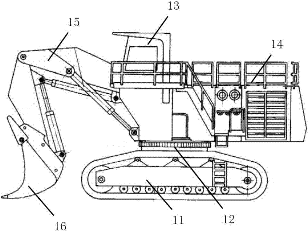
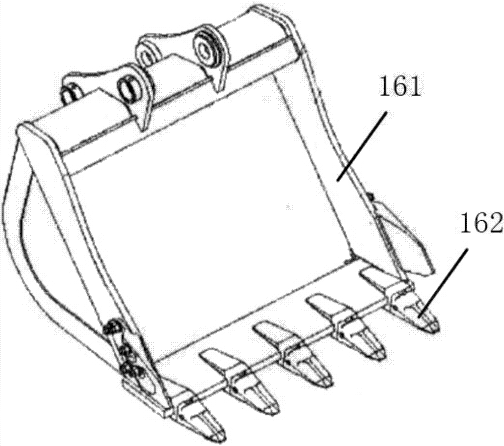
[0047] refer to Figure 1 to Figure 3 , the mining excavator with the monitoring function of bucket teeth 162 provided in this embodiment includes: a chassis 11 and a rotary platform 12, and the rotary platform 12 is provided with a driver's cab 13, an electrical room 14 and a stick 15, and the bucket A bucket 16 is connected to the end of the rod 15; the bucket 16 includes a bucket body 161 and a plurality of bucket teeth 162, the bucket body 161 is connected with the bucket rod 15, and the bucket teeth 162 are connected with the bucket body 161 connection; each of the bucket teeth 162 is provided with a detection device for monitoring the breakage of the bucket teeth 162, the detection device is connected to the monitoring system signal, and the driver's cab 13 is provided with an alarm connected to the monitoring system signal. device.

[0048] The bucket 16 includes a bucket body 161 and bucket teeth 162. A detection device for monitoring the breakage of the bucket teeth ...

Embodiment 2

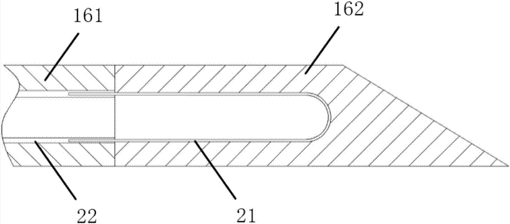
[0054] In the mining excavator with the monitoring function of the bucket teeth 162 provided in this embodiment, the U-shaped conductors 21 in the plurality of the bucket teeth 162 are arranged in parallel.

[0055] Wherein, each U-shaped conductor 21 is independent, so that according to the position of the low-level signal, it is possible to determine which bucket tooth 162 is broken, and to give a reminder.

Embodiment 3

[0057] refer to Figure 4 and Figure 5 , The mining excavator with the monitoring function of the bucket teeth 162 provided in this embodiment further includes an air supply system, and the air outlet of the air supply system is communicated with the electrical room 14 .

[0058] In this embodiment, the monitoring of the state of the bucket teeth 162 is mainly realized by the detection device and the monitoring system connected to the detection device, and depends on the stable operation of the monitoring system. If the monitoring system fails, it will cause an inability to issue an alarm or false alarm, affecting the work. efficiency, and even cause damage to the excavator or the supporting crushing station. However, due to the high power of the mining excavator, the electrical equipment in the electrical room 14 emits a large amount of heat, causing the temperature in the electrical room 14 to rise. When the temperature is high, the electrical equipment may malfunction. T...


PUM


Abstract

The invention provides a mine excavator with a bucket tooth monitoring function. The mine excavator comprises a chassis and a rotating platform. A cab, an electrical room and a bucket rod are arranged on the rotating platform. A bucket is connected at the tail end of the bucket rod and comprises a bucket body and a plurality of bucket teeth. The bucket body is connected with the bucket rod. The bucket teeth are connected with the bucket body. A detecting device used for monitoring bucket tooth fracturing is arranged in each bucket tooth and is in signal connection with a monitoring system. An alarming device in signal connection with the monitoring system is arranged in the cab. According to the mine excavator with the bucket tooth monitoring function, the bucket tooth monitoring function is achieved, the bucket fracturing phenomenon can be discovered timely, and warning is conducted.

Description

technical field [0001] The application relates to the field of mining machinery, in particular to a mining excavator with a bucket tooth monitoring function. Background technique [0002] Mining excavators mainly refer to excavators used in coal mines, iron mines and other mines. They have the characteristics of large bucket capacity, high power and large digging force. They mainly include chassis, sticks, buckets, driver's cabs, electrical rooms, etc. . However, due to the characteristics of high power and large bucket digging force, the phenomenon of bucket teeth breakage is easy to occur during the working process. After the bucket teeth are broken, if they are not found in time and the teeth are repaired, it is easy for the end face of the bucket floor to directly collide with the ore, resulting in floor wear and shortening the service life. Directly enter the crushing station for crushing. If the broken bucket teeth cannot be found in time, the broken bucket teeth wil...

Claims


Application Information

Patent Timeline
IPC IPC(8): E02F9/28E02F9/26E02F9/00B01D50/00
CPCE02F9/00E02F9/267E02F9/28B01D50/10
Inventor 张艳玲
Owner 湖南美奕机电科技有限公司
Why Eureka
Try Eureka