
Snap spring feeding device

A technology of feeding device and circlip, applied in metal processing, metal processing equipment, manufacturing tools, etc., can solve the problems of affecting installation speed, high labor intensity, and low efficiency

Pending Publication Date: 2017-07-25
HUZHOU AIXIANTE ELECTRONIC TECH CO LTD
View PDF9 Cites 2 Cited by
  • Summary
  • Abstract
  • Description
  • Claims
  • Application Information

AI Technical Summary

Problems solved by technology

[0004] However, this method of operation also has certain disadvantages. On the one hand, the process of pressing the spring into the parts requires manual operation by the user, which is labor-intensive and low in efficiency. On the other hand, workers can only press one piece at a time, which affects the installation. speed

Method used


Image

  • Snap spring feeding device
  • Snap spring feeding device

Examples


Embodiment 1

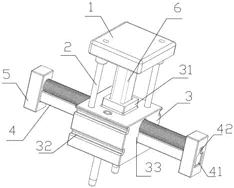
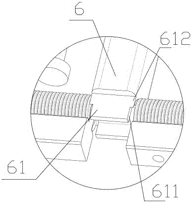
[0035] Example 1, such as figure 1 and figure 2 As shown, a circlip feeding device includes a fixed clip 4, and also includes a lower pressure member 6 and a heel block 5 that is slidably connected with the fixed frame 4; a plurality of circlips are arranged on the fixed clip 4, and the heel block 5 is used for Drive the circlip to move in the direction of the downward pressing member 6, and the lower pressing member 6 includes a pressure head 61 for pressing the circlip from the fixing clip 4, and the pressure head 61 includes an inlet 611 and a resisting patch located above the inlet 611 612 , the entrance 611 is further away from the direction of the heel block 5 than the interference patch 612 .

[0036] The jig 3 is also included, and the side end of the jig 3 is provided with a side opening 33 for connecting the fixing clip 4 , and a passage opening for the lower pressing member 6 to pass through is opened in the vertical direction. Both sides of the jig 3 are provide...


PUM


Abstract

The invention relates to the field of mechanical parts, in particular to a snap spring feeding device. The snap spring feeding device comprises a fixed clamp, and further comprises a pressing piece and a followup block slidingly connected with the fixed clamp; multiple snap springs are arranged on the fixed clamp; the followup block is used for driving the snap springs to move in the direction of the pressing piece; the pressing piece includes a pressing head for pressing the snap springs from the fixed clamp; the pressing head includes an inlet, and a butting patch positioned above the inlet; and the inlet is further from the direction of the followup block compared with the butting patch. The invention aims to provide the snap spring feeding device; and the snap spring feeding device is high in matching degree with automatic equipment, simple in structure, convenient to use, stable in pressing effect in the snap spring pressing process and low in labor intensity of workers.

Description

technical field [0001] The invention relates to the field of mechanical components, in particular to a clamp spring feeding device. Background technique [0002] Circlips are also called retaining rings or clasps, which are a type of fasteners. They are installed in the shaft grooves or hole grooves of machines and equipment to prevent the axial movement of parts on the shaft or holes. In many mechanical parts, the circlip is used. [0003] The process of using the circlip is relatively simple. Workers often take the circlip manually, and then manually press the circlip into the component. The whole process is simple and smooth, and does not require the use of tools. [0004] However, this method of operation also has certain disadvantages. On the one hand, the process of pressing the spring into the parts requires manual operation by the user, which is labor-intensive and low in efficiency. On the other hand, workers can only press one piece at a time, which affects the in...

Claims


Application Information

Patent Timeline
IPC IPC(8): B23P19/00
CPCB23P19/001
Inventor 俞尧王士泽
Owner HUZHOU AIXIANTE ELECTRONIC TECH CO LTD
Learn More