Positioning punching die

A punching die and nesting technology, used in manufacturing tools, metal processing equipment, stripping devices, etc., can solve the problem that the metal punching die cannot be punched at one time, cannot meet the requirements of product miniaturization, and the finished products are disorderly distributed, etc. problems, to achieve the effect of reducing punching costs, reducing mold costs and ensuring quality

Active Publication Date: 2017-07-28
达翔技术(恩施)有限公司
View PDF8 Cites 2 Cited by
  • Summary
  • Abstract
  • Description
  • Claims
  • Application Information

AI Technical Summary

Problems solved by technology

[0005] However, the above metal punching die separates the waste area by punching and retains the finished product area, which is suitable for the punching of "hollowed out" large-format finished products; if a single small product is punched, the above metal punching die cannot be punched at one time Form...

Method used


Image

  • Positioning punching die
  • Positioning punching die
  • Positioning punching die

Examples


Embodiment Construction

[0029] The technical solutions of the present invention will be further described below in conjunction with the accompanying drawings and through specific implementation methods.

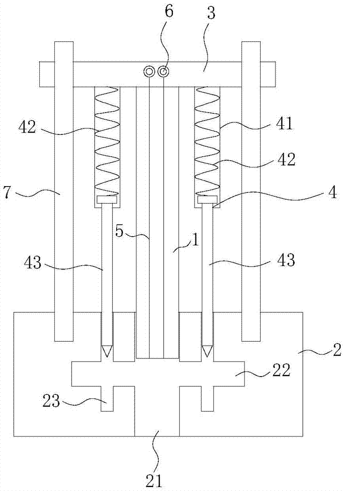
[0030] The invention provides a set punching die, such as figure 2 As shown, it includes a punch 1 and a die 2, the lower end of the punch 1 is provided with a punch edge, which cooperates with the die 2 to complete the punching of the material to be punched;

[0031] A punching opening 21 and a feed opening 22 perpendicular to the punching opening 21 are provided through the die 2, and the material to be punched enters the die 2 from the feed opening 22 and is arranged below the punch 1, and the punch 1 One end is located above the punching slot 21 and can be moved into the punching slot 21 , and punches the plate to be punched along the punching slot 21 . In this embodiment, the punching notch 21 is set through the die 2 , and then the punch 1 will continue to move after the punch 1 completes pu...


PUM


Abstract

The invention discloses a positioning punching die. The positioning punching die comprises a male die and a female die. The female die is provided with a punching opening and a feeding opening perpendicular to the punching opening in a cut-through manner. One end of the male die is located above the punching opening and can move into the punching opening, the other end of the male die is connected with a fixing plate, and the fixing plate is fixedly connected with a plurality of sets of positioning assemblies fixing materials to be punched. The male die is internally provided with a plurality of gas channels in a cut-through manner, the gas channels communicate with a gas pipe connector on the fixing plate, and the gas pipe connector is connected with a gas sucking device. According to the positioning punching die, the male die is provided with the gas channels, when punching is carried out, the gas sucking device adsorbs the materials to be punched through the gas channels, then, the male die and the female die are matched to complete punching, after punching is completed, the male die continues to press to send a finished product to an appointed position, an adsorbing device is stopped to put the finished product down, the punching efficiency of the die can be improved, the quality of the finished product obtained after punching is guaranteed, the punching cost is reduced, and the punching requirements of small products are met.

Description

technical field [0001] The invention relates to the technical field of punching dies, in particular to a nested punching die. Background technique [0002] The punching die is usually installed on various presses and machinery equipped with pressure devices, and the specified material is punched out of the desired shape by pressing the die. [0003] Existing metal punching dies such as figure 1 As shown, it includes a discharge plate 101 , a fixed plate 102 , a punch 103 , a die plate 104 , an upper mold base 105 and a lower mold base 106 . Among them, the fixed plate 102 plays the role of fixing the punch 103; the unloading plate 101 mainly plays three functions of unloading, guiding, and pressing; the die plate 104 can be used as the cutting edge of the die, and the die can also be inlaid on it. Insert. Four guide pillars 107 are used to guide and fix between the unloading plate 101, the fixing plate 102, and the concave template 104. [0004] When the above metal punc...

Claims


Application Information

Patent Timeline
IPC IPC(8): B21D28/14B21D45/08
CPCB21D28/14B21D45/08
Inventor 胡荣赵磊陈进财黄思才严峥刘乐新
Owner 达翔技术(恩施)有限公司
Why Eureka
Try Eureka