Faucet assembly with aerator cartridge and method for mounting the assembly

A technology of faucet assembly and bubbler, which is applied in the direction of pipes/pipe joints/fittings, indoor sanitary pipeline devices, passing components, etc., and can solve problems such as unresolved, adding bubbler sleeves, etc.

Active Publication Date: 2017-07-28
AMFAG
View PDF10 Cites 7 Cited by
  • Summary
  • Abstract
  • Description
  • Claims
  • Application Information

AI Technical Summary

Problems solved by technology

In both cases, this solution offers only one advantage of cost reduction of the sealing ring, without solving or even increasing the difficulty of removing the bubbler sleeve due to the high tightening torque

Method used


Image

  • Faucet assembly with aerator cartridge and method for mounting the assembly
  • Faucet assembly with aerator cartridge and method for mounting the assembly
  • Faucet assembly with aerator cartridge and method for mounting the assembly

Examples


Embodiment Construction

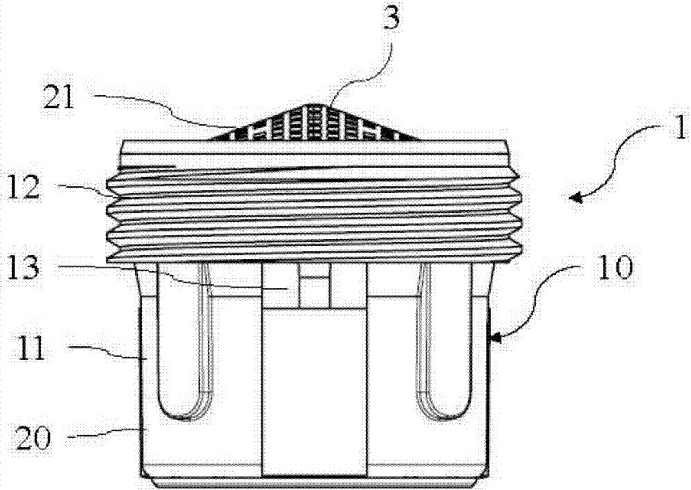
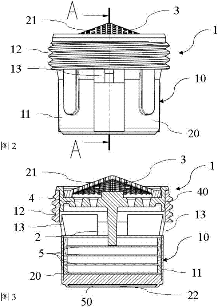
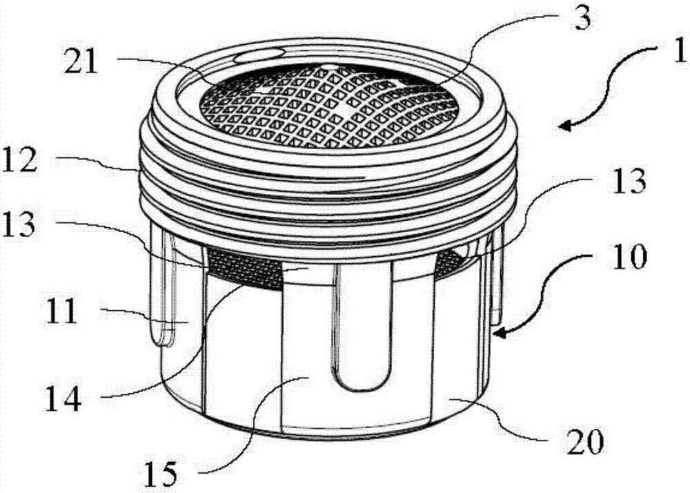
[0068] Reference attached Figure 1-5 , Where the reference numeral 1 generally represents the first embodiment of the bubbler sleeve.

[0069] On the other hand, the reference symbol 1'represents Image 6 The second embodiment of the bubbler sleeve is shown, and the reference numeral 1" represents the Figure 7 The example shown in the bubbler sleeve is not part of the present invention. In the last two figures, the bubbler sleeve shown is housed in an operating position inside the termination channel of the tap, below which termination channel is indicated as port 100.

[0070] Figure 8 with Picture 9 Finally, two variants of the bubbler sleeve 1 according to the first embodiment are shown, which are provided with special protrusions for manually unscrewing the bubbler sleeve.

[0071] The present invention relates to a faucet assembly, which includes one of bubbler sleeves 1, 1'. The faucet assembly includes a base part, which is not shown in the drawings because it is known pe...


PUM


Abstract

A faucet assembly with an aerator cartridge (1'). The aerator cartridge is screwed by means of an attachment thread (12) into a mouth (100), which has no sealing gasket, wherein water (W) seeping through the attachment thread (12) is at least partially reintroduced into a casing (10) of cartridge (1') through suitably positioned aeration windows (13), being dragged by the air flow (A). The air flow is sucked into the aeration windows (13) by the water flow within an internal flow path (2) of the cartridge (1).

Description

Technical field [0001] The present invention relates to a faucet assembly with a bubbler sleeve (aerator cartridge), the bubbler sleeve is specifically hidden, that is, the bubbler sleeve can be completely inserted in the In the mouth of the dragon head. The invention also relates to a method of installing the bubbler sleeve in its base. [0002] The above-mentioned equipment is advantageously used in the field of faucets and faucet accessories. Background technique [0003] Foaming (aerator) equipment has been widely used in various household water installations. After being installed on the fluid outlet from the water supply network, specifically on the faucet, this aerator device allows the flow of water to pass through. It is mixed with air to avoid liquid penetration and homogenization, so that a complete conventional jet is obtained. Because it uses less water flow to achieve the jet flow required by the user, this equipment significantly reduces water consumption and ener...

Claims


Application Information

Patent Timeline
Patent Type & Authority Applications(China)
IPC IPC(8): E03C1/08E03C1/084
CPCE03C1/08E03C1/084E03C1/086F16L15/006
Inventor 奥兰多·博肖
Owner AMFAG
Why Eureka
Try Eureka