
Stepless speed changer

一种无级变速器、腔体的技术,应用在车辆变速箱、传动装置、流体传动装置等方向,能够解决不具备柔性传动功能、装置结构复杂、制造成本高等问题,达到实现大功率柔性传动场合、传动过程柔性、实现自动匹配的效果

Pending Publication Date: 2017-08-01
WEIHAI TUANZHONG TRANSMISSION CO LTD
View PDF8 Cites 6 Cited by
  • Summary
  • Abstract
  • Description
  • Claims
  • Application Information

AI Technical Summary

Problems solved by technology

[0003] (1) The torque converter is a pump wheel whose power is connected through the casing. The pump wheel stirs the oil in the torque converter, drives the turbine to rotate through the guide wheel, and the turbine outputs power. The disadvantage is that when the torque converter When the speed difference between the pump wheel and the turbine is close to synchronization, the transmission ability will be lost and synchronization cannot be achieved; in order to improve the above problems existing in the hydraulic torque converter, when the control system is added, the system will be complicated and the manufacturing cost will be high.
[0004] (2) The existing continuously variable transmission (CVT) uses transmission friction and a driving belt with variable working diameter to transmit power, which can realize the continuous change of the transmission ratio, so as to obtain the working conditions of the transmission system and the engine. Its disadvantage is that it cannot provide flexible zero start, cannot provide large torque, and it is easy to slip when the force changes frequently.
[0005] (3) The existing domestic patent authorization number is CN 102606709 B patented hydraulic synchronous double speed device, the disadvantage of this hydraulic synchronous double speed device is that the balance force between the bucket wheel and the oil is limited, and it can only The maximum balance force of the bucket wheel is internally variable; when the output shaft needs to be greater than the torque that the maximum balance force of the oil and the bucket wheel can provide, the oil in the inner box needs to be emptied, and the gear mechanism involved in braking is a commonly used The structure of the planetary gear reducer does not have the function of flexible transmission; the whole control system belongs to the electronic control system, and the structure of the control, braking and other devices is complex
[0006] (4) The applicant has submitted a patent application for a continuously variable transmission with a patent acceptance number of 201710055648.2. The technical solution is that the bucket wheel planetary gear set is located on the side of the output end cover of the cavity. The disadvantage of this structure is : When the transmission system starts or accelerates and needs to quickly increase the output torque, the planetary gear set at the input end and the planetary gear set at the output end increase the torque through two times of diameter enlargement. The revolution speed of the planet carrier determines the rotation speed of the planetary wheel of the bucket wheel. The power density of the bucket wheel with this structure increases slowly, which is not suitable for the working conditions that need to quickly increase the output torque.

Method used


Image

  • Stepless speed changer
  • Stepless speed changer
  • Stepless speed changer

Examples


Embodiment 1

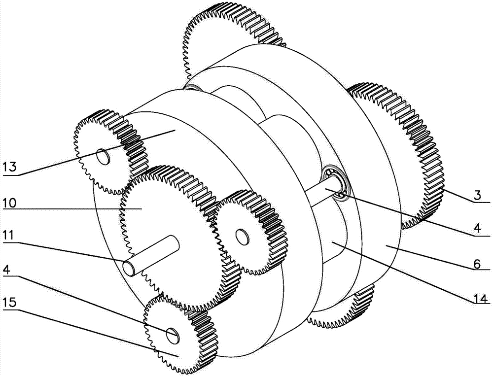
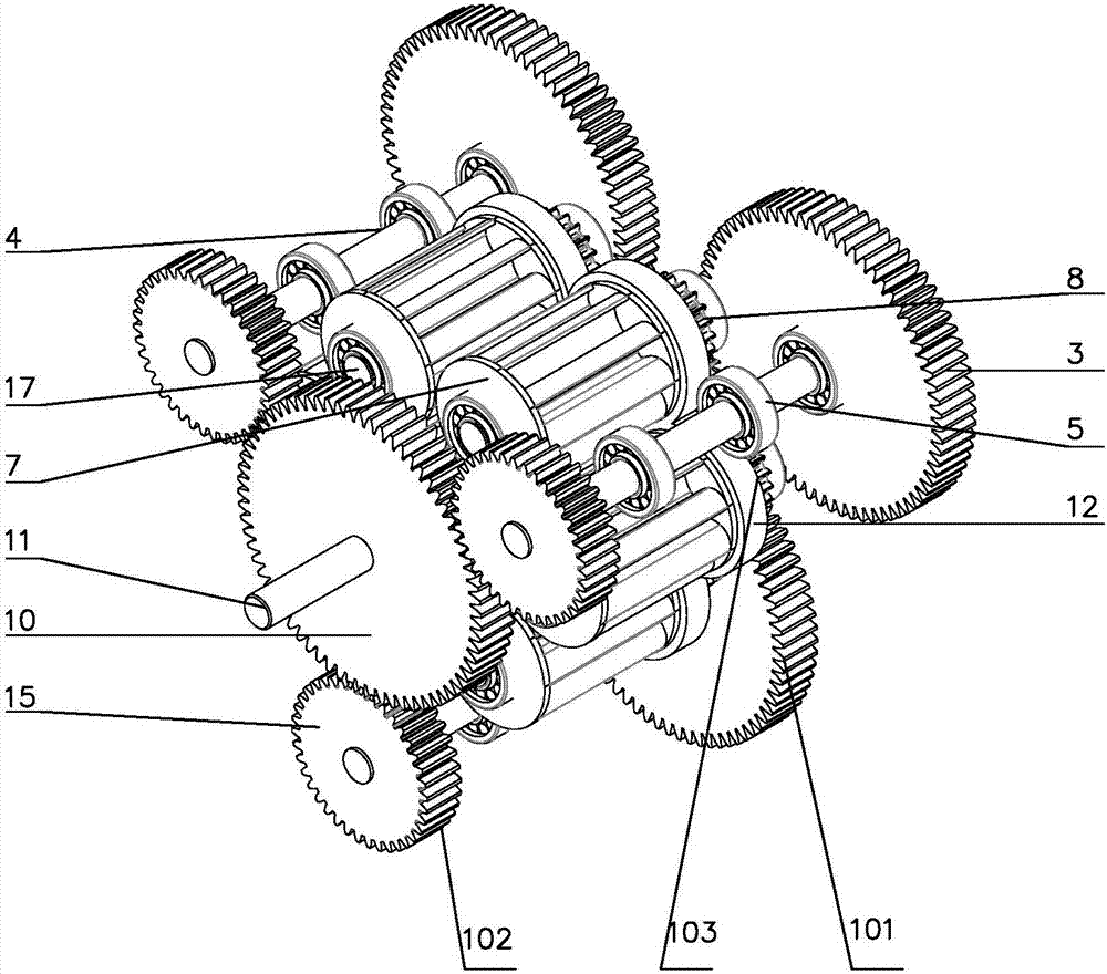
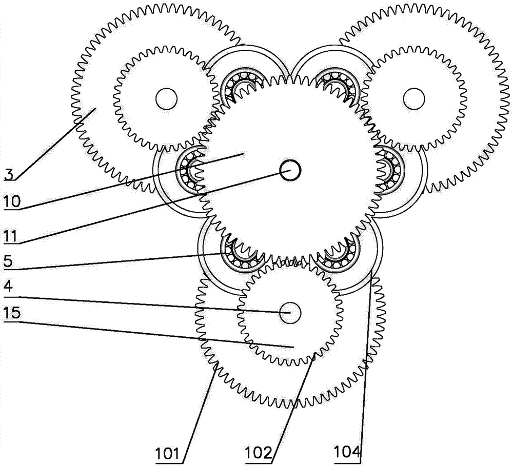
[0038] Such as Figure 1-Figure 5As shown, it is an embodiment of a continuously variable transmission of the present invention, which is provided with an input planetary gear set 101 and an output planetary gear set 102, and between the input planetary gear set 101 and the output planetary gear set 102 is a The cavity planet carrier 104, the cavity planet carrier 104 includes the cavity input end cover 6, the cavity output end cover 13, and the bucket wheel cavity shell is fixed between the cavity input end cover 6 and the cavity output end cover 13 14. The inner side of the planetary gear set 101 at the input end is connected to the input end cover 6 of the cavity, the inner side of the planetary gear set 102 at the output end is connected to the output end cover 13 of the cavity, and the side of the input end cover 6 of the inner cavity of the bucket wheel cavity housing 14 There is a bucket wheel planetary gear set 103; the input end planetary gear set 101 includes an inpu...

Embodiment 2

[0048] Figure 6-Figure 9 It is the second embodiment of the present invention. It is provided with a bucket wheel planetary gear set 103 and an output end planetary gear set 102. The inner side of the bucket wheel planetary gear set 103 is provided with a cavity planet carrier 104, and the cavity planet carrier 104 includes a cavity input end cover. 6. The cavity output end cover 13, the bucket wheel cavity housing 14 is fixed between the cavity input end cover 6 and the cavity output end cover 13, and the cavity input end cover 13 and the bucket wheel cavity housing 14 are fixed. There is an input planetary gear set 101 between them; the bucket wheel planetary gear set 103 includes a bucket wheel sun gear 9 and nine bucket wheel planetary gears 8, the bucket wheel sun gear 9 and the bucket wheel planetary gear 8 are meshed and connected, and the bucket wheel sun gear There is an input shaft 1 in the middle of 9, and the input shaft 1 passes through the input end cover 6 of t...


PUM


Abstract

The invention provides a stepless speed changer which solves the problems that when a traditional stepless speed changer is started, a power density lifting speed of a bucket wheel is low, and a working condition requiring a high output torque lifting speed can not be adapted. The stepless speed changer is characterized in that the stepless speed changer comprises an input end planetary gear set and an output end planetary gear set; a cavity planet carrier is arranged between the input end planetary gear set and the output end planetary gear set, and comprises a cavity input end cover and a cavity output end cover; a bucket wheel cavity housing is fixedly arranged between the cavity input end cover and the cavity output end cover; the inner side of the input end planetary gear set is connected with the cavity input end cover; the inner side of the output end planetary gear set is connected with the cavity output end cover; and a bucket wheel planetary gear set is arranged on one side of the interior of the bucket wheel cavity housing. The stepless speed changer can be widely applied in the field of transmission.

Description

technical field [0001] The invention relates to a mechanical transmission device, in particular to a continuously variable transmission. Background technique [0002] In the field of transmission, the transmission is the most widely used in the automotive field. At present, automobile transmissions are divided into manual transmission (MT), automatic transmission (AT) and manual automatic transmission according to the operation mode. With the rapid development of automobiles, automatic transmissions have gradually occupied the mainstream of automobiles due to their simple operation, and automatic transmission vehicles achieve the purpose of speed change through hydraulic transmission and gear combination. Automatic transmissions are further divided into hydraulic automatic transmissions (AT), electromechanical automatic transmissions (AMT) and continuously variable transmissions (CVT). Among them, the most widely used and most loaded components are hydraulic torque converte...

Claims


Application Information

Patent Timeline
Patent Type & Authority Applications(China)
IPC IPC(8): F16H47/08
CPCF16H47/08F16H47/12F16H2702/00F16H2702/02
Inventor 唐永峰付岩帅
Owner WEIHAI TUANZHONG TRANSMISSION CO LTD
Learn More