Lamp band structure adjustable in irradiation angle and lamp band mounting structure

A technology of irradiation angle and light strip, which is applied in the field of home decoration or tooling, can solve the problems of small effective irradiation area and large loss of light energy, and achieve the effects of reducing light energy consumption, saving electric energy, and reducing use

Pending Publication Date: 2017-08-01
钟焕锋
View PDF2 Cites 4 Cited by
  • Summary
  • Abstract
  • Description
  • Claims
  • Application Information

AI Technical Summary

Problems solved by technology

[0004] Aiming at the problems of large loss of light energy and small effective irradiation area due to the low installation position and fixed irradiation angle of the existing conventional light strips in the light trough, the present invention provides a light strip structure with adjustable irradiation angles and Light strip installation structure

Method used


Image

  • Lamp band structure adjustable in irradiation angle and lamp band mounting structure
  • Lamp band structure adjustable in irradiation angle and lamp band mounting structure
  • Lamp band structure adjustable in irradiation angle and lamp band mounting structure

Examples


Embodiment 1

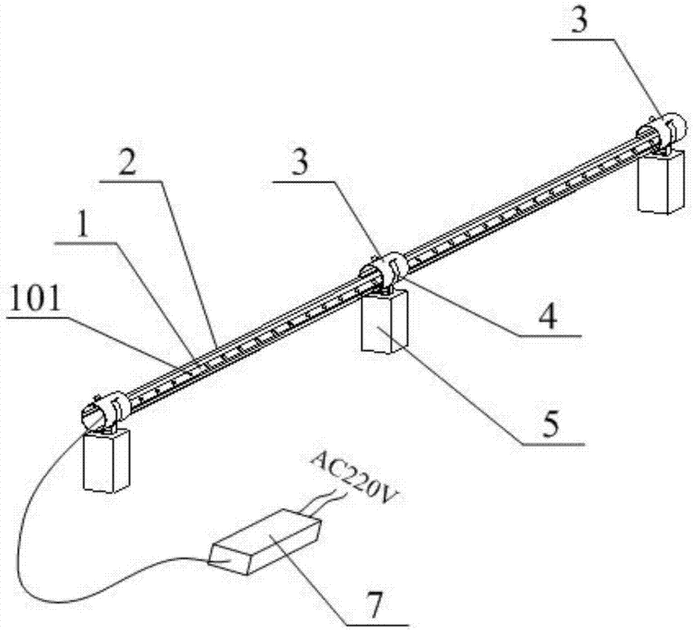
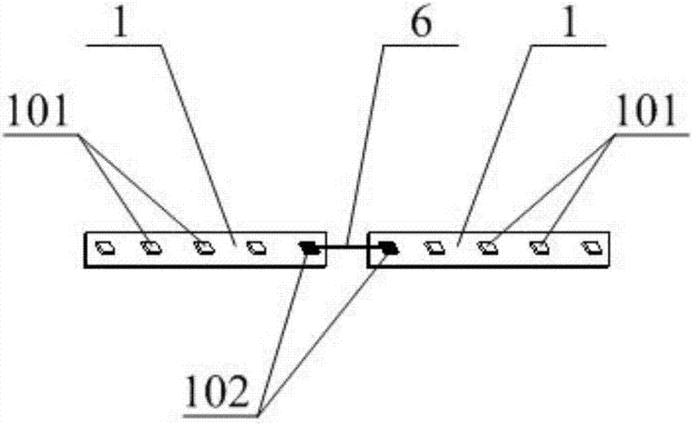
[0025] figure 2 Shows the structural schematic diagram of the light strip with adjustable illumination angle provided by the present invention, image 3 Shows the connection diagram of the strip light source board in the light strip structure provided by the present invention, Figure 4 Shows the assembly schematic diagram of the rotating sleeve, the rotating sleeve holder and the pillar in the light belt structure provided by the present invention, Figure 5 It shows a schematic diagram of the installation structure of the light strip with adjustable illumination angle provided by the present invention.

[0026] The light strip structure with adjustable illumination angle provided by this embodiment includes a strip light source plate 1, a strip lamp housing 2, a rotating sleeve 3, a rotating sleeve holder 4 and a column 5, wherein the A number of lamp beads 101 are arranged in a single line on the strip-shaped light source board 1, and the height of the column 5 is 10-15 mm lowe...

Embodiment 2

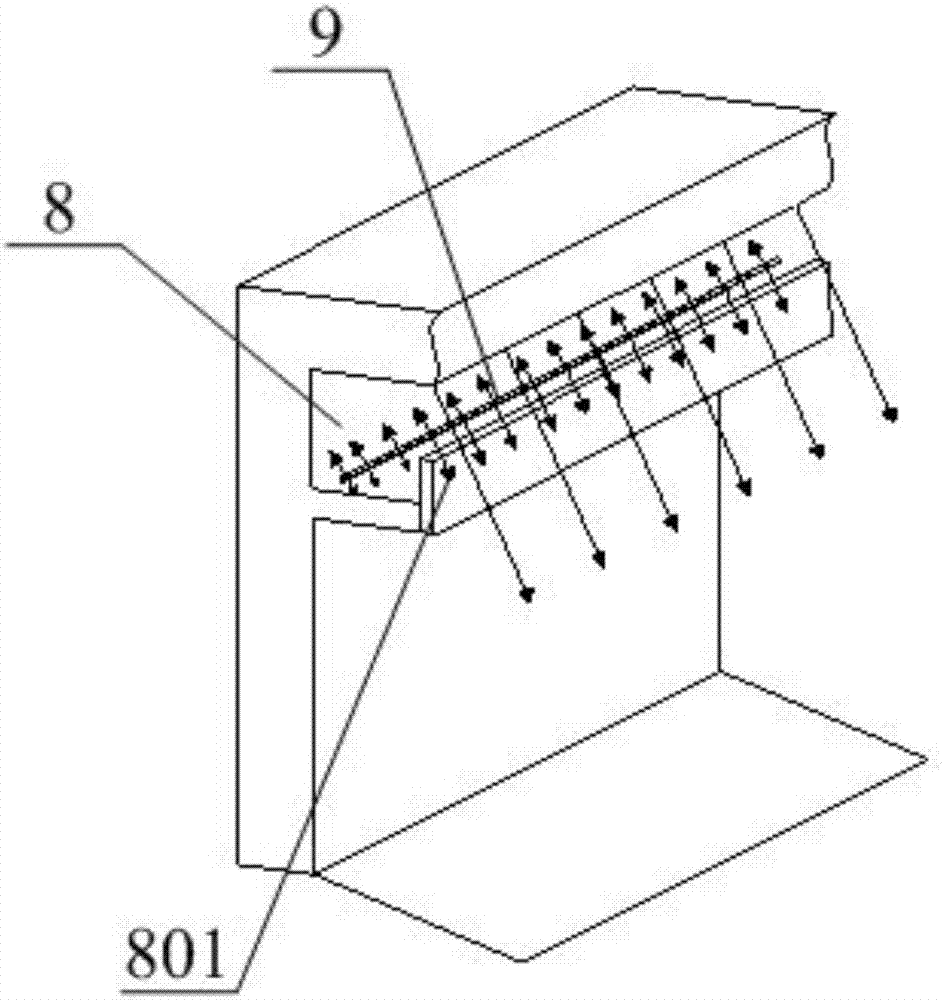
[0036] This embodiment is used as a specific application scheme of the light strip structure described in the first embodiment, and the light strip installation structure with adjustable illumination angle provided by it is as follows: linearly arranged in the light trough 8 located on the peripheral edge of the top of the room as in the first embodiment The lamp belt structure with adjustable illumination angle. Through this light strip installation structure, the central area of ​​the ceiling can be made high-brightness due to the convergence of lights on the four sides, reducing the use of additional lighting fixtures, especially for rooms within 30 square meters, which can be illuminated by the light source It can meet the lighting requirements, save the cost of installing lighting lamps, and make the ceiling more tidy and beautiful. At the same time, due to the surrounding arrangement of the light strip structure, the light strip light source can emit light around, so that...


PUM


Abstract

The invention relates to the field of home decoration or tooling, and particularly discloses a lamp band structure adjustable in irradiation angle and a lamp band mounting structure. The lamp band structure adjustable in irradiation angle is characterized in that a strip-shaped lamp housing, a rotating sleeve, rotating sleeve clamping parts and vertical pillars are arranged for a strip-shaped light source plate in the lamp band structure, on one hand, light rays emitted from the strip-shaped light source plate are adjusted in irradiation angle, so that more light rays can project onto the ceiling, the ground surface, the wall surface and the room, the environment embellishing effect of the lamp band is improved to a lighting effect on the overall room, and the conventional direct lighting method is changed; on the other hand, the shading effect of a light trough environment on the light rays is reduced, light energy consumption in the inner area of the light trough is reduced, and the purpose of saving the electric energy is achieved; meanwhile, as the light source of the lamp band is hidden in the light trough, not only is the lighting effect improved, but also the light rays emitted from the lamp band light source are prevented from being incident on human eyes directly, the problem that the conventional lighting lamp is high in brightness but dazzling is solved, and the life and work of people is facilitated.

Description

Technical field [0001] The invention relates to the field of home improvement or tooling, and in particular to a light belt structure with adjustable illumination angle and a light belt installation structure. Background technique [0002] In the current home improvement or tooling, the light strip is usually arranged at the bottom of the light trough located at the top edge of the room to provide an environmental embellishment effect for the room lighting. However, it is limited by the illumination angle of the light strip and the height of the light trough shading plate, which actually plays a role. The lighting effect is not strong. Such as figure 1 The existing light strip installation structure shown mainly has the following three defects: (1) It is restricted by the light-emitting angle of the conventional light strip 9 (approximately 120°) and the shading effect of the shading plate 801 of the lamp slot 8, as shown by the arrow , The light consumes light energy in the inn...

Claims


Application Information

Patent Timeline
Patent Type & Authority Applications(China)
IPC IPC(8): F21S4/24F21V15/02F21V19/00F21V17/16F21V23/00H05B37/02F21V21/36F21V21/30F21V14/02
CPCF21V14/02F21V15/02F21V17/164F21V19/00F21V21/30F21V21/36F21V23/003H05B47/10Y02B20/40
Inventor 钟焕锋
Owner 钟焕锋
Why Eureka
Try Eureka