Welding device

A technology of welding device and sliding connection, which is applied to the parts of the connecting device, coupling device, welding accessories, etc., can solve the problems of plug joint loosening, user loss, pin bending deformation, etc., so as to prevent the plug from loosening and increase safety Effects on sex and stability

Inactive Publication Date: 2017-08-04
陈柯
View PDF6 Cites 22 Cited by
  • Summary
  • Abstract
  • Description
  • Claims
  • Application Information

AI Technical Summary

Problems solved by technology

[0002] With the continuous maturity of welding technology, the use of electric welding machines is becoming more and more extensive. In some welding factories, it is necessary to move the position frequently during welding to meet the welding needs of different directions. However, the power supply of existing welding machines The plug connector setting mode is too simple, so that the tightness after plugging is not high, and it is very easy to be dragged, pulled and other external factors to make the plug connector loose, resulting in poor contact and unable to supply power for welding normally, which has great disadvantages. , The protection ability of the plug joints of the existing welding machines is poor. Excessive force or repeated plugging during the plugging process may cause the pins to bend and deform, shorten the service life, and cause losses to users.

Method used


Image

  • Welding device
  • Welding device
  • Welding device

Examples


Embodiment Construction

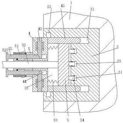
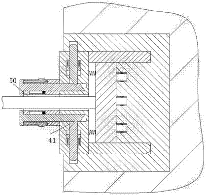
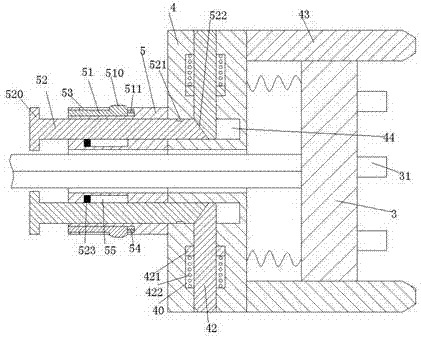
[0019] Combine below Figure 1-5 The present invention will be described in detail.

[0020] refer to Figure 1-5 , a welding device according to an embodiment of the present invention, including a power distribution base 2 fixedly installed in a distribution box 1, a power terminal 3 matched with the power distribution base 2, and a power terminal for protecting the power distribution base 2. The protection device for the electric terminal 3, the left and right sides of the distribution box 1 are equipped with fixing rings 101 on the upper and lower sides, and the fixing rings 101 are provided with fixing holes 102, and the fixing rings 101 are used for For the fixing of the distribution box 1, the power distribution seat 2 is provided with a sliding connection cavity 25 with the mouth facing left, and an insertion slot 22 is provided in the right end wall of the sliding connection cavity 25, and an insertion slot 22 is set in the insertion slot 22. There is a power supply ...


PUM


Abstract

A welding device comprises a power distribution seat which is fixedly mounted in a power distribution box, a power connection end which is in match with the power distribution seat, and a protecting device for protecting the power connection end, wherein a sliding connection chamber of which a port part is leftwards formed is arranged in the power distribution seat; an inserting groove is formed in the right end wall of the slide connection chamber; an inserting pin which fits the inserting groove is fixedly arranged at the right end of the power connection end; the protecting device comprises a slide connection rack which is in slide fitting with the slide connection seat, and straight plates which are transversely symmetrically mounted at the right end of the slide connection rack; a housing sleeve is fixedly arranged in the left end of the slide connection rack; guide connection grooves which are in match with the straight plates are transversely symmetrically arranged in the right end wall of the slide connection chamber; locking grooves are symmetrically formed in the upper end wall and the lower end wall of the slide connection chamber; first slide connection groove are symmetrically formed in the slide connection rack in an extending manner; locking rods in match with the locking grooves are mounted in the first slide connection grooves in a slide connection manner; locking devices for locking the locking rods to fit the corresponding locking grooves are arranged at the housing sleeve; and unlocking devices for releasing the fitting of the locking rods and the locking grooves are arranged at the housing sleeve.

Description

technical field [0001] The invention relates to the technical field of welding, in particular to a welding device. Background technique [0002] With the continuous maturity of welding technology, the use of electric welding machines is becoming more and more extensive. In some welding factories, it is necessary to move the position frequently during welding to meet the welding needs of different directions. However, the power supply of existing welding machines The plug connector setting mode is too simple, so that the tightness after plugging is not high, and it is very easy to be dragged, pulled and other external factors to make the plug connector loose, resulting in poor contact and unable to supply power for welding normally, which has great disadvantages. , The protection ability of the plug connector of the existing welding machine is poor. Excessive force or repeated plugging during the plugging process may cause the pins to bend and deform, shorten the service life...

Claims


Application Information

Patent Timeline
Patent Type & Authority Applications(China)
IPC IPC(8): B23K9/32H01R13/502H01R13/633H01R13/635H01R13/639
CPCB23K9/32H01R13/502H01R13/633H01R13/635H01R13/639
Inventor 陈柯
Owner 陈柯
Why Eureka
Try Eureka