Electric leakage overvoltage test circuit and electric leakage overvoltage tester

A technology for testing circuit and leakage voltage, applied in short-circuit testing, measuring current/voltage, instruments, etc., can solve the problem of not being able to give leakage voltage at the same time, and achieve the effect of convenient leakage detection and maintenance

Inactive Publication Date: 2017-08-04
TIANJIN ZHONGLING SHINENG TECH CO LTD
View PDF4 Cites 0 Cited by
  • Summary
  • Abstract
  • Description
  • Claims
  • Application Information

AI Technical Summary

Problems solved by technology

[0005] In view of this, the object of the present invention is to provide a leakage overvoltage testing circuit to solve the technical problem that the leakage detection equipment in the prior art cannot simultaneously provide whether the leakage voltage is overvoltage and the type of leakage

Method used


Image

  • Electric leakage overvoltage test circuit and electric leakage overvoltage tester
  • Electric leakage overvoltage test circuit and electric leakage overvoltage tester
  • Electric leakage overvoltage test circuit and electric leakage overvoltage tester

Examples


Embodiment 1

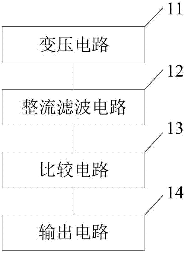
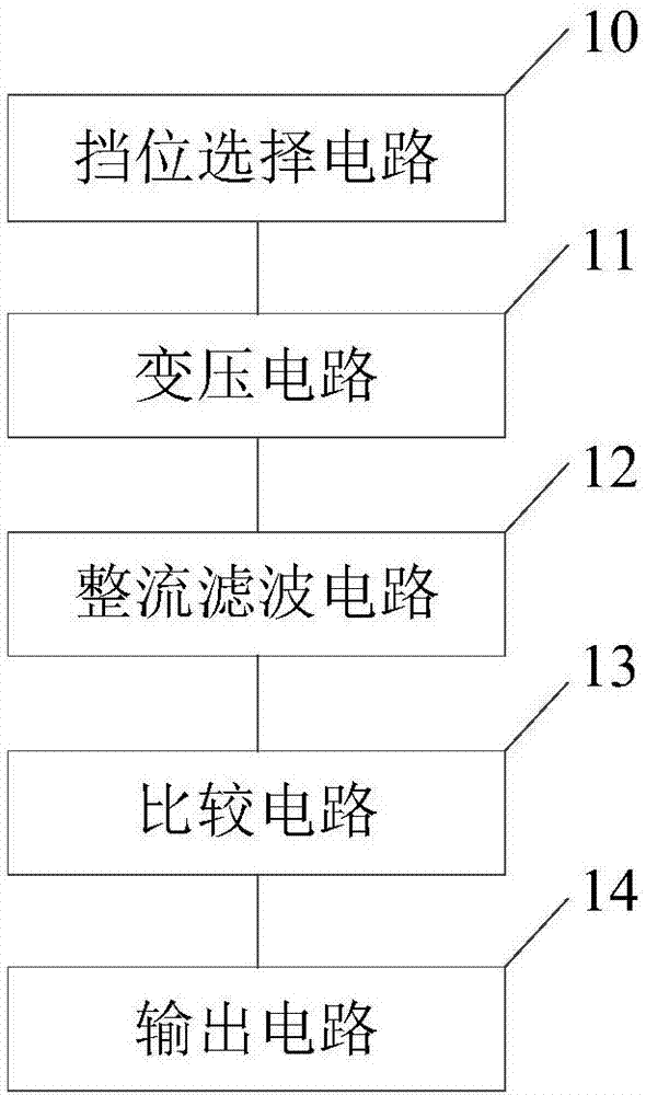
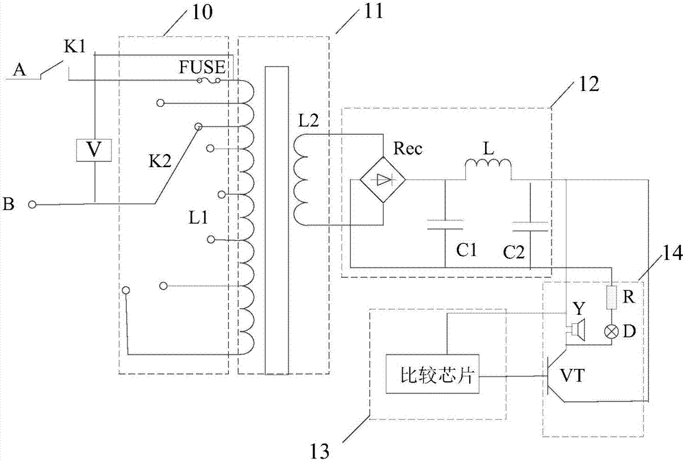
[0039] Such as figure 1 As shown, a leakage overvoltage test circuit includes: a transformer circuit 11, a rectification filter circuit 12, a comparison circuit 13, an output circuit 14 and a voltmeter V; the transformer circuit 11 is used to transform the leakage voltage and output it to The rectification and filtering circuit 12; the rectification and filtering circuit 12 is used to rectify and filter the leakage voltage after the transformation; the comparison circuit 13 is used to compare the rectified and filtered leakage voltage with the reference voltage, and output the comparison result to the output circuit 14; The output circuit 14 displays the comparison result; the voltmeter V is set at the input end of the transformer circuit 11 , the rectification filter circuit 12 , the comparison circuit 13 or the output circuit 14 .

[0040] In this embodiment, the leakage voltage is transformed by the transformer circuit and output to the rectification and filtering circuit; ...

Embodiment 2

[0061] This embodiment provides a leakage and overvoltage tester, including the leakage and overvoltage testing circuit 1 described in Embodiment 1.

[0062] Such as Figure 5 As shown, the leakage overvoltage tester in this embodiment also includes a display screen 2 for displaying the leakage voltage.

[0063] This embodiment preferably further includes a reference voltage input circuit for inputting a reference voltage, and the reference voltage input circuit enables workers to set the reference voltage according to experience and detection scenarios.

[0064] The leakage and overvoltage tester provided by the embodiment of the present invention has the same technical features as the leakage and overvoltage test circuit provided by the above embodiments, so it can also solve the same technical problems and achieve the same technical effect.

[0065] Such as Image 6 As shown, the present embodiment provides a method for using a leakage tester, comprising the following ste...


PUM


Abstract

The invention provides an electric leakage overvoltage test circuit and electric leakage overvoltage tester, and relates to the technical field of electric leakage detection. The electric leakage overvoltage test circuit includes a voltage transformation circuit, a rectification and filtering circuit, a comparison circuit, an output circuit and a voltmeter; the voltage transformation circuit is used for performing voltage transformation on electric leakage voltage and outputting the electric leakage voltage to the rectification and filtering circuit; the rectification and filtering circuit is used for performing rectification and filtering on the electric leakage voltage after voltage transformation; the comparison circuit is used for comparing the electric leakage voltage after rectification and filtering with reference voltage and outputting a comparison result to the output circuit; the output circuit displays the comparison result; and the voltmeter is arranged at the input end of the voltage transformation circuit, the rectification and filtering circuit, the comparison circuit or the output circuit, the technical problem in the prior art that whether current electric leakage voltage is overvoltage and an electric leakage type cannot be given at the same time is solved, and the technical effect of automatically prompting overvoltage of active electric leakage voltage is achieved.

Description

technical field [0001] The invention relates to the technical field of leakage detection, in particular to a leakage overvoltage test circuit and a leakage overvoltage tester. Background technique [0002] In the process of overhauling power transmission lines or electrical equipment, when leakage to the ground occurs, the leakage line and the ground form a loop, and at the same time, voltage is generated and current flows. This voltage can drive electrical equipment to work, which is almost the same as the power supply voltage. Usually this voltage is called active voltage. It can be measured with a voltmeter or multimeter. [0003] However, not all voltages measured by voltmeters or multimeters can drive electrical equipment to do work and make electrical equipment work. That is to say, the voltages measured by voltmeters or multimeters may not have load capacity. The voltage is called reactive voltage, this voltage will not drive the load to work, let alone cause harm t...

Claims


Application Information

Patent Timeline
Patent Type & Authority Applications(China)
IPC IPC(8): G01R31/02G01R19/06G01R19/165
CPCG01R19/06G01R19/16576G01R19/16595G01R31/52
Inventor 马健马骥
Owner TIANJIN ZHONGLING SHINENG TECH CO LTD
Why Eureka
Try Eureka