Environmentally-friendly dust-removal facility

A facility and environmental protection technology, applied in the direction of preventing contact with live contact devices, electrical components, coupling devices, etc., can solve the problems of electric shock hazard of the transmission head, power failure of the dust collector, and no protective parts for the transmission hole, so as to reduce the electric shock. Accidents, the effect of increasing safety and stability

Active Publication Date: 2017-08-04
盐城欧路华纤维科技有限公司
View PDF5 Cites 16 Cited by
  • Summary
  • Abstract
  • Description
  • Claims
  • Application Information

AI Technical Summary

Problems solved by technology

[0002] Dust collectors are commonly used dust treatment equipment. When people use dust collectors, they need to drag them around to treat dust in various places. Dust collectors need electricity when they are in use, but the power transmission holes in the existing power supply frame are always In the power-on state, and the power transmission hole is not equipped with a cover that can be covered, it is easy to cause an electric shock hazard when plugging in the power transmission head. In addition, because the power transmission hole is not equipped with a lock for the power transmission head, if someone accidentally kicks and hits the cable by mistake. It will lead to sudden power failure of the dust collector

Method used


Image

  • Environmentally-friendly dust-removal facility
  • Environmentally-friendly dust-removal facility
  • Environmentally-friendly dust-removal facility

Examples


Embodiment Construction

[0020] The preferred embodiments of the present invention will be described in detail below in conjunction with the accompanying drawings, so that the advantages and features of the present invention can be more easily understood by those skilled in the art, so as to define the protection scope of the present invention more clearly.

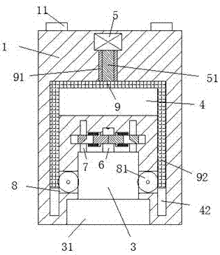
[0021] refer to Figure 1-6 The shown environment-friendly dust removal facility includes a frame body 1 and a power transmission head 2 protruding into the frame body 1 to be connected. There is a hanging opening 12 with the entrance facing down between the corner and the power transmission head 2, and the frame body 1 can be hung through the hanging buckle 12 between the hanging angle 11 and the power transmission head frame 1, thereby saving floor space , the frame body 1 is provided with a clamping groove 31 with the entrance forward, the rear end of the clamping groove 31 is provided with a socket groove 3 communicating with the clamping gro...


PUM


Abstract

The present invention discloses an environmentally-friendly dust-removal facility. The environmentally-friendly dust-removal facility comprises a frame body and a power transmission head which extends into the frame body and is in matched connection with the frame body; the upper part of the rear end surface of the power transmission head is provided with a hanging corner; a hanging opening which faces downwards is formed between the hanging corner and the power transmission head; a clamping groove of which the inlet faces forwards is formed in the frame body; a plugging opening groove which is communicated with the clamping groove is formed at the middle of the rear end portion of the clamping groove; a power transmission hole communicated with the plugging opening groove is formed at the middle of the rear end portion of the plugging opening groove; and supporting and matching grooves which are communicated with the plugging opening groove and are located at the left side and right side of the power transmission hole are correspondingly formed in the frame body; and covering devices which are used for covering the power transmission hole and are located at the left side and right side of the power transmission hole are correspondingly formed in the frame body. The environmentally-friendly dust-removal facility of the invention has the advantages of overall simple structure, safe and stable power supply and overall safe and reliable operation, and can assist in decreasing electric shock accidents in life and is suitable for being popularized.

Description

technical field [0001] The invention relates to the field of dust removal facilities, in particular to an environment-friendly dust removal facility. Background technique [0002] Dust collectors are commonly used dust treatment equipment. When people use dust collectors, they need to drag them around to treat dust in various places. Dust collectors need electricity when they are in use, but the power transmission holes in the existing power supply frame are always In the power-on state, and the power transmission hole is not equipped with a cover that can be covered, it is easy to cause an electric shock hazard when plugging in the power transmission head. In addition, because the power transmission hole is not equipped with a lock for the power transmission head, if someone accidentally kicks and hits the cable by mistake. It will lead to sudden power failure of the dust collector. Contents of the invention [0003] The technical problem to be solved by the present inve...

Claims


Application Information

Patent Timeline
Patent Type & Authority Applications(China)
IPC IPC(8): H01R13/44H01R13/639
CPCH01R13/44H01R13/639
Inventor 何冠阅
Owner 盐城欧路华纤维科技有限公司
Why Eureka
Try Eureka