An optical all-pass filter, a microwave photon filter and a phase shifter

An all-pass filter and filter technology, which is applied in the field of optical filters and microwave photons, can solve the problems of limiting the working range of microwave photon phase shifters, the limited operating frequency range of phase shifters, and narrow bandwidth of microwave photon filters. , to achieve the effect of no jitter in amplitude response, reduced device size, and good bandwidth

Active Publication Date: 2019-08-13
HUAZHONG UNIV OF SCI & TECH
View PDF3 Cites 0 Cited by
  • Summary
  • Abstract
  • Description
  • Claims
  • Application Information

AI Technical Summary

Problems solved by technology

However, the phase filtering bandwidth of the all-pass filter based on cascaded microrings is very large (meaning that the phase change from 0 to 2π is realized only in a wide frequency range), and the large bandwidth limits the performance of the constructed microwave photonic filter. Bandwidth, which also limits the operating range of microwave photonic phase shifters, and introduces unwanted amplitude changes while phase shifting due to the presence of a dip in the amplitude at the resonance point
Therefore, the bandwidth of the microwave photonic filter based on the cascaded microring all-pass filter cannot be narrow enough, and the operating frequency range of the phase shifter based on the cascaded microring all-pass filter is limited, and introduces unwanted amplitude Variety

Method used


Image

  • An optical all-pass filter, a microwave photon filter and a phase shifter
  • An optical all-pass filter, a microwave photon filter and a phase shifter
  • An optical all-pass filter, a microwave photon filter and a phase shifter

Examples


Embodiment Construction

[0038] In order to make the object, technical solution and advantages of the present invention clearer, the present invention will be further described in detail below in conjunction with the accompanying drawings and embodiments. It should be understood that the specific embodiments described here are only used to explain the present invention, not to limit the present invention. In addition, the technical features involved in the various embodiments of the present invention described below can be combined with each other as long as they do not constitute a conflict with each other.

[0039] The technical solutions of the present invention will be further specifically described below in conjunction with the accompanying drawings and specific embodiments.

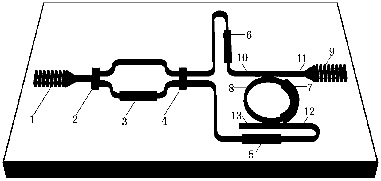
[0040] Such as figure 1 The structural schematic diagram of the optical all-pass filter shown, including a 1 × 2 optical coupler, a 2 × 2 optical coupler, a microring and a plurality of optical phase shifters; wherein, the...


PUM


Abstract

The invention discloses an optical all-pass filter. The optical all-pass filter comprises a first optical coupler, a second optical coupler, a first coupling grating, a second coupling grating, first, second, third and fourth optical phase shifters and a microring. By use of frequency response characteristics of the microring, two ways of signals with adjustable amplitudes and phases are transmitted into the microring from two different ports of the microring respectively and are output at the two ports of the microring after being subjected to interfered beam combination. Different system phase response spectrum widths are realized by changing the coupling state of the microring, system amplitude response is a constant unrelated to frequency through adjustment of the amplitudes and phases of the two ways of signals, so that the optical all-pass filter is obtained. On the basis of the optical all-pass filter, the invention discloses a microwave photonic filter with a high Q value and an ultrahigh inhibition ratio and a microwave photonic phase shifter with a broad work frequency range and no sinking of amplitude response in the work range.

Description

technical field [0001] The invention belongs to the technical field of optical filters and microwave photons, relates to an integrated optical all-pass filter, and realizes a microwave photon filter and a microwave photon phase shifter on the basis of the optical all-pass filter. Background technique [0002] An optical all-pass filter is a phase filter whose amplitude response is constant and whose phase response varies with frequency. Through the corresponding design of the phase, it can be used to construct optical delay lines, dispersion compensators, etc., and is an important device in all-optical signal processing systems. [0003] Optical all-pass filters usually have two structures: Gires-Tournois cavity and microring structure. Among them, the Gires-Tournois cavity and the circulator can realize the function of the optical all-pass filter, but this structure is bulky and complex. Microrings are small in size, compatible with semiconductor processes, and can be adj...

Claims


Application Information

Patent Timeline
Patent Type & Authority Patents(China)
IPC IPC(8): G02F1/01G02F1/21
CPCG02F1/0102G02F1/21G02F1/212
Inventor 于源刘小龙张新亮
Owner HUAZHONG UNIV OF SCI & TECH
Why Eureka
Try Eureka