A reducing die pipe device and diameter reducing method for easy casting and demolding

A technology for mold pipes and pipes, which is applied in the fields of mold shells/templates/work frames, erection/assembly of bridges, and on-site preparation of building components, etc. The overall structure is simple and the design is reasonable.

Active Publication Date: 2019-07-26
南京仁创模具科技有限公司
View PDF6 Cites 2 Cited by
  • Summary
  • Abstract
  • Description
  • Claims
  • Application Information

AI Technical Summary

Problems solved by technology

[0003] The purpose of the present invention is to overcome the deficiencies of the prior art. The purpose is to provide a variable diameter mold pipeline device and a variable diameter method that are convenient for pouring and demoulding, and solve the problem of inconvenient disassembly of the mold for casting long-sized through holes in the existing building.

Method used


Image

  • A reducing die pipe device and diameter reducing method for easy casting and demolding
  • A reducing die pipe device and diameter reducing method for easy casting and demolding
  • A reducing die pipe device and diameter reducing method for easy casting and demolding

Examples


Embodiment 1

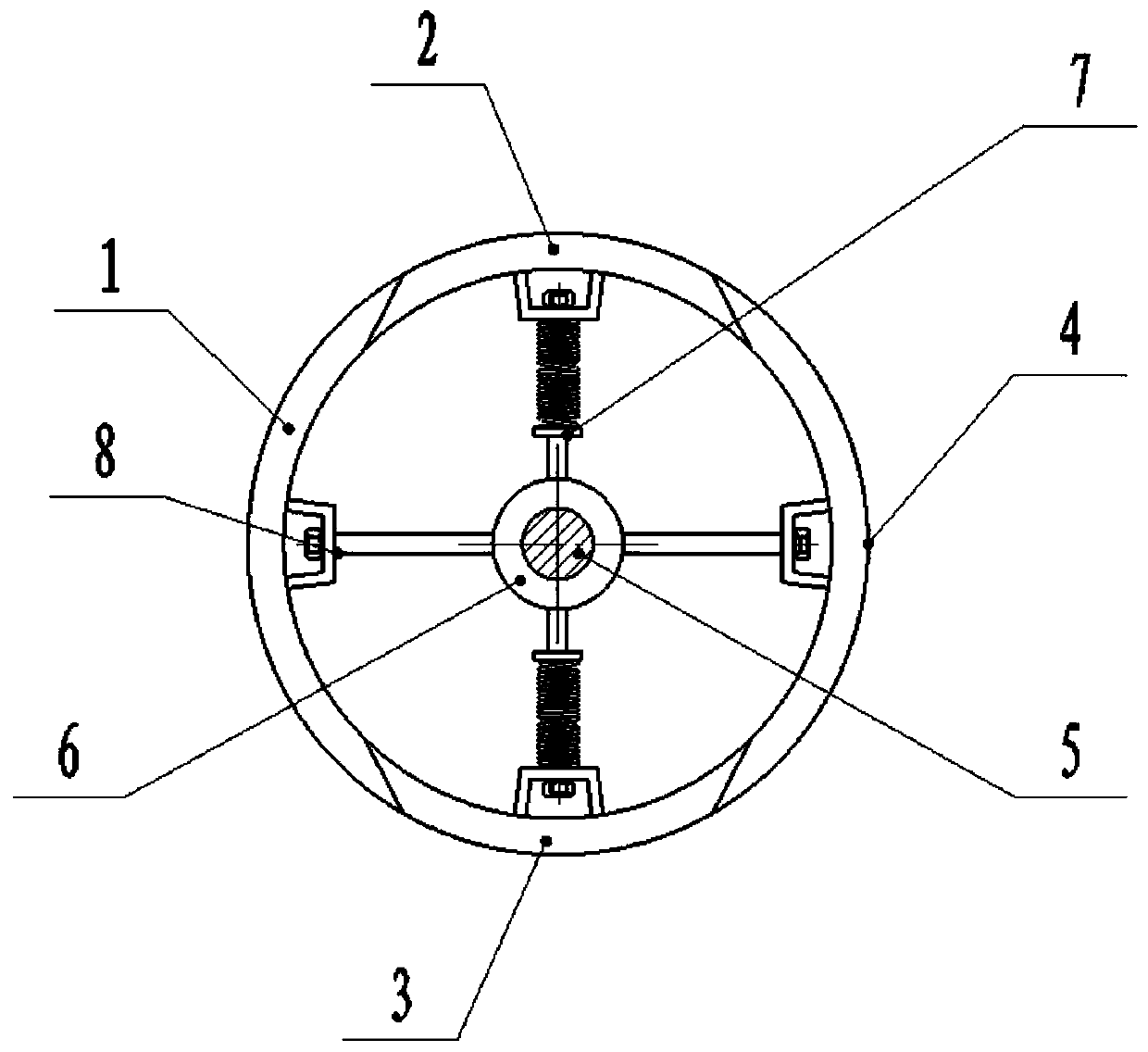
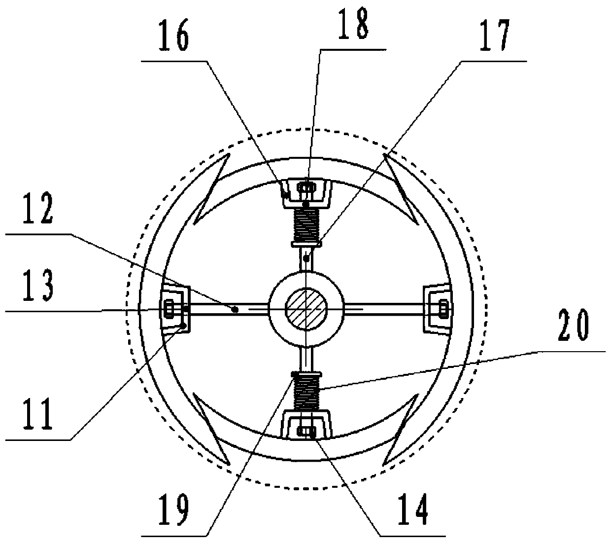
[0029] Such as Figure 1-3 As shown, the present invention is a variable-diameter mold pipeline device that is convenient for pouring and demoulding, including a mold pipeline, and the mold pipeline is cut into two symmetrical four-piece pipeline segments along the axial direction, which are respectively the first pipeline sector 1, the second The pipe segment 2, the third pipe segment 3 and the fourth pipe segment 4, the two sides of the first pipe segment 1 and the corresponding sides of the second pipe segment 2 and the third pipe segment 3 adopt oblique faces, and the fourth pipe segment The two sides of the fan piece 4 and the corresponding sides of the second pipeline fan piece 2 and the third pipeline fan piece 3 also adopt oblique faces, and the center of the mold pipeline is provided with a rotating shaft 5. When the mold pipeline is 2m long and the diameter is 0.2m, the rotating shaft 5 Four shaft sleeves 6 are evenly distributed on the top, which can be flexibly ope...

Embodiment 2

[0036] Such as Figure 1-3 As shown, a method for reducing the diameter of mold pipes of the present invention, which is convenient for pouring and demoulding, comprises steps:

[0037] Step 1) Reversely rotate the rotating shaft 5 by the hand wheel 21, so that the first pipe segment 1, the second pipe segment 2, the third pipe segment 3 and the fourth pipe segment 4 are reset to form a complete mold pipe;

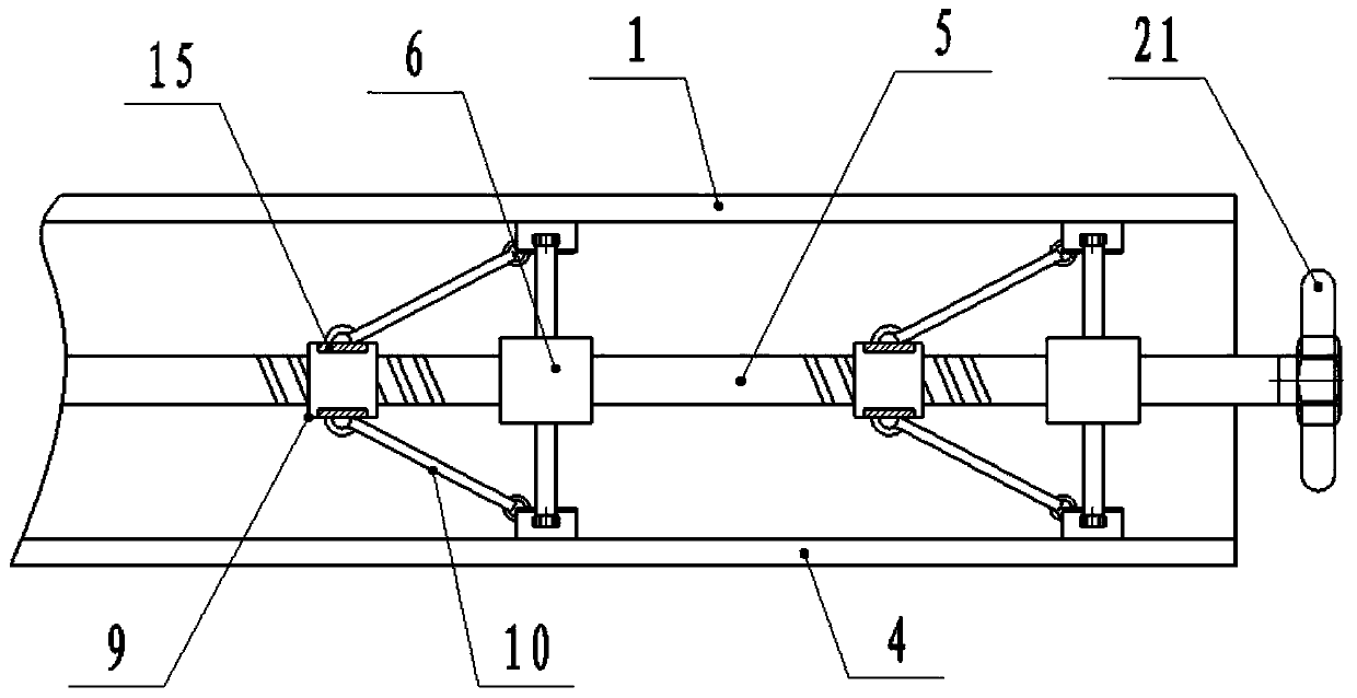
[0038] Step 2) After the pouring is completed, when the mold pipe needs to be taken out, the rotating shaft 5 is rotated forward by the hand wheel 21, and the rotation of the rotating shaft 5 drives the wire sleeve 9 and the sliding sleeve 15 on the wire sleeve 9 to move down along the rotating shaft 5, and the sliding sleeve 15 Pull the first U-shaped buckle 11 through the connecting shaft 10 to move along the first guide shaft 12 to the axial direction of the mold pipe, and through the pulling of the first U-shaped buckle 11, the first pipe segment 1 and the fourth pipe ...


PUM


Abstract

The invention discloses a variable diameter mould pipeline device convenient for pouring demoulding and a variable diameter method. The variable diameter mould pipeline device convenient for pouring demoulding comprises a mould pipeline, the mould pipeline is cut into four pipeline sector parts in the axial direction in a two-two symmetrical mode, the four pipeline sector parts are the first sector part, the second sector part, the third sector part and the fourth sector part respectively; the two sides of the first sector part and the corresponding sides of the second sector part and the third sector part are connected in a butt joint mode through inclined planes, and the two sides of the fourth sector part and the corresponding sides of the second sector part and the third sector part are also connected in a butt joint mode through inclined planes; and a rotary shaft is arranged in the center of the mould pipeline, a plurality of shaft sleeves are evenly distributed and arranged on the rotary shaft, the shaft sleeves are connected with the second sector part and the third sector part through elastic extensible pieces correspondingly, the shaft sleeves are connected with the first sector part and the fourth sector part through elastic extensible pieces correspondingly, a screw sleeve in threaded fit is arranged on the rotary shaft below each shaft sleeve, and the screw sleeves are connected with the extensible pieces through connection shafts.

Description

technical field [0001] The invention relates to the field of construction engineering, in particular to a diameter-changing mold pipeline device and a diameter-changing method that are convenient for pouring and demoulding. Background technique [0002] In the field of construction or road and bridge construction, it is often necessary to use pouring to build components. When pouring the building, it is often necessary to reserve through holes in the building to lay pipes or lay cables. The reservation of the through holes requires the support of the mold. If The length of the through hole is short, and the ordinary mold can be used for easy installation and disassembly. If the through hole is more than 1 meter, the ordinary mold cannot be disassembled after pouring, but can only be demolished. This will cause damage to the building and cause damage to the mold. waste. Contents of the invention [0003] The purpose of the present invention is to overcome the deficiencies ...

Claims


Application Information

Patent Timeline
Patent Type & Authority Patents(China)
IPC IPC(8): E04G15/00E04G15/06E01D21/00
CPCE01D21/00E04G15/00E04G15/065
Inventor 李永芬
Owner 南京仁创模具科技有限公司
Why Eureka
Try Eureka