Methods and systems for an exhaust aftertreatment device

A technology of exhaust post-treatment and post-processing devices, which is applied in the direction of exhaust devices, combustion methods, noise reduction devices, etc., can solve the problems of catalyst quality impact, reduce catalyst packaging restrictions, etc., and achieve easy ignition conditions and meet ignition conditions Effect

Active Publication Date: 2017-08-11
FORD GLOBAL TECH LLC
View PDF5 Cites 5 Cited by
  • Summary
  • Abstract
  • Description
  • Claims
  • Application Information

AI Technical Summary

Problems solved by technology

In addition, the packaging of the above mentioned catalysts is not sufficient to reduce the pack...

Method used


Image

  • Methods and systems for an exhaust aftertreatment device
  • Methods and systems for an exhaust aftertreatment device
  • Methods and systems for an exhaust aftertreatment device

Examples


Embodiment Construction

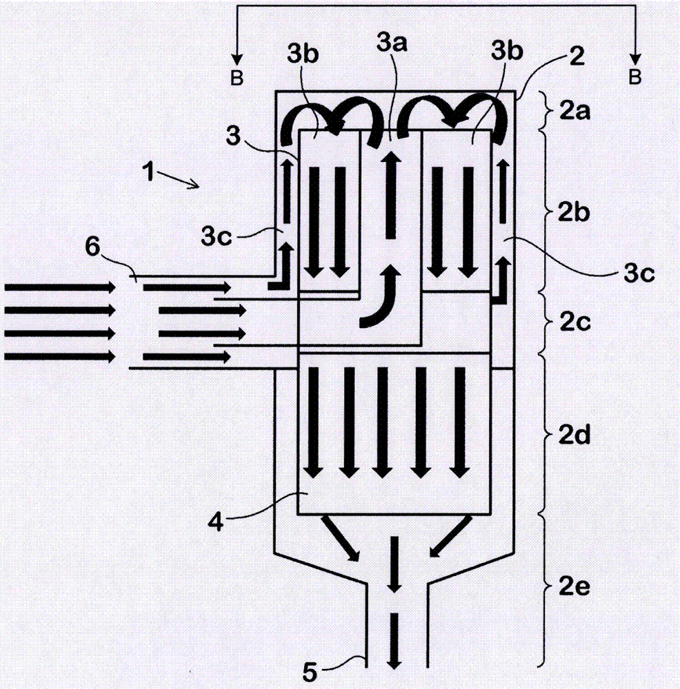
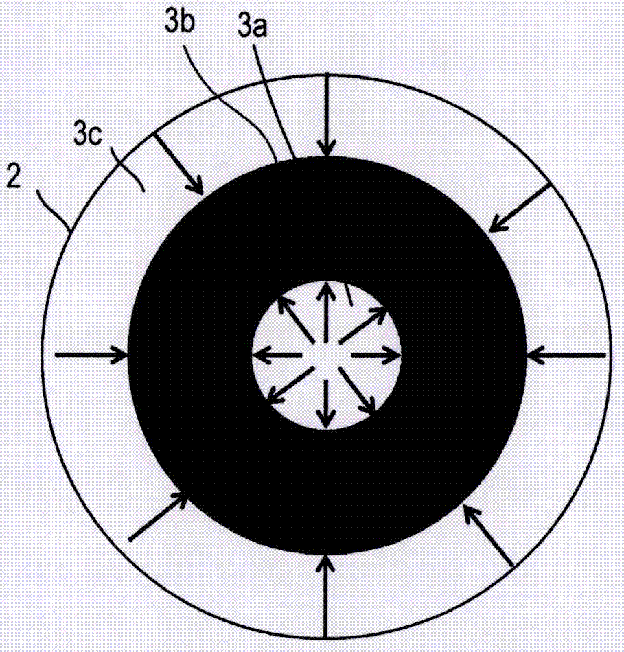
[0036] The following description relates to systems and methods for exhaust aftertreatment devices. The catalyst and particulate filter are located in the exhaust aftertreatment housing. The catalyst is a toroid with a central channel in its central opening and an outer channel between the catalyst and the aftertreatment housing. Exhaust from the exhaust outlet flows into the central and outer passages before flowing into the catalyst, such as figure 1 shown. As the exhaust gas flows through these passages in a first direction, the exhaust gas preheats the catalyst before flowing into the catalyst, as figure 2 shown. Exhaust gases flow out of the central and outer passages into a first end of the housing, while exhaust gases in a second direction may mix at the first end before flowing through the catalyst. In one example, the second direction is opposite the first direction such that the exhaust flow in the housing is generally U-shaped. By arranging the catalyst and pa...


PUM


Abstract

The invention relates to methods and systems for an exhaust aftertreatmetn device. Systems are provided for an exhaust gas aftertreatment device, in particular in a motor vehicle, having a catalyst accommodated in a housing which, along its length, has a first end section, a catalyst section, and a connecting section. The housing further comprises a particulate filter located downstream of the catalyst.

Description

[0001] Cross References to Related Applications [0002] This application claims priority from German Patent Application No. 102016201557.5 filed on February 2, 2016. The entire content of the above application is hereby incorporated by reference in its entirety for all purposes. technical field [0003] The present invention relates generally to methods and systems for exhaust aftertreatment devices, and more particularly to methods and systems for exhaust aftertreatment devices in motor vehicles, the device having a catalyst contained in a housing along which The length has a first end section, a catalyst section and a connecting section and relates to the arrangement of this type of exhaust aftertreatment device in a motor vehicle. Background technique [0004] Exhaust gas aftertreatment device, by means of which it is possible to comply with the limits imposed by future emission standards for the emission of pollutants from motor vehicles with internal combustion engine...

Claims


Application Information

Patent Timeline
IPC IPC(8): F01N3/28F01N3/02F23D14/18
CPCF01N3/02F01N3/28F23D14/18F23G7/07Y02T10/12F01N3/021F01N3/0835F01N3/0842F01N3/101F01N3/103F01N3/2892
Inventor G·H·格劳希F·格贝尔R·弗里切R·拉赫F·韦伯
Owner FORD GLOBAL TECH LLC
Why Eureka
Try Eureka