Magnet therapy mattress with magnetic field distribution changed along with press position

A magnetic field distribution and mattress technology, applied in the field of magnetic therapy mattresses, can solve the problems of weakening the effect of magnetic therapy and unreasonable position, and achieve the effect of good magnetic therapy effect and dense magnetic field

Active Publication Date: 2017-08-18
HEYE HEALTH TECH CO LTD
View PDF6 Cites 3 Cited by
  • Summary
  • Abstract
  • Description
  • Claims
  • Application Information

AI Technical Summary

Problems solved by technology

For users with different body sizes, the distribution of the magnetic field they receive is different, and the position of the magnetic field release cannot

Method used


Image

  • Magnet therapy mattress with magnetic field distribution changed along with press position
  • Magnet therapy mattress with magnetic field distribution changed along with press position
  • Magnet therapy mattress with magnetic field distribution changed along with press position

Examples


Embodiment 1

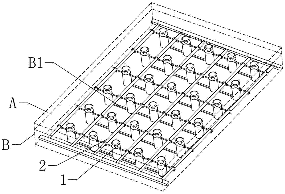
[0031] according to Figure 1 ~ Figure 3 As shown, a magnetic therapy mattress that changes the magnetic field distribution with the pressure position includes: a bed surface layer A and a functional layer B, and a plurality of pressure response mechanisms 1 and a plurality of magnet sliders 2 are arranged in the functional layer B and used The slider track 3 that slides on the magnet slider 2, the pressure response mechanism 1 and the magnet slider 2 are arranged at intervals, and the two ends of the magnet slider 2 are arranged in the slider track 3;

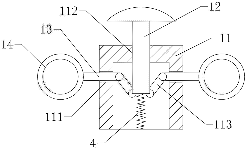
[0032] The pressure response mechanism 1 includes a support body 11, a compression rod 12 and a retraction rod 13, a return spring 4 is arranged between the support body 11 and the compression rod 12, and the two sections of the retraction rod 13 are respectively an A end and a B end, A The end is provided with an insertion ring 14, and the B end is connected with the support body 11 or the pressure rod 12. The magnet slider 2...

Embodiment 2

[0039] The difference from the above-mentioned embodiment 1 is that, according to Figure 4 As shown, the compression rod 12 is plugged outside the support body 11 , and the end of the contraction rod 13B is hinged to the outer surface of the compression rod 12 .

[0040] In this embodiment, after the compression rod 12 is subjected to a pressure drop, the end of the shrink rod 13A will be retracted toward the center of the pressure response mechanism 1, and the horizontal height of the magnet slider 2 will not change under the constraints of the slider track 3. Collapse between the same horizontal plane. It can also play the role of concentrating the magnetic field to the pressure sinking area.

Embodiment 3

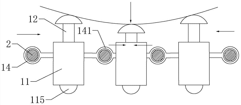
[0042] The difference from the above-mentioned embodiment 1 is that, according to Figure 5 As shown, two groups of shrink rods 13 are connected outside the compression rod 12, each group includes two shrink rods 13, the two groups of shrink rods 13 are perpendicular to each other and the lengths of the two groups of shrink rods 13 are different, correspondingly, the magnet slide rod 2 also Divided into a horizontal group and a vertical group, there is a height difference between the horizontal group and the vertical group, and a spherical pulley 115 is provided at the bottom of the support body 11 .

[0043] In this embodiment, two groups of magnet sliders distributed in upper and lower layers change the magnetic field distribution from a single linear direction to a grid distribution, which improves the magnetic therapy effect.


PUM


Abstract

The invention relates to the field of magnet therapy healthcare, in particular to a magnet therapy mattress with the magnetic field distribution changed along with the press position. The magnet therapy mattress comprises a bed surface layer and a functional layer. A plurality of pressure response mechanisms, a plurality of magnet slide bars and slide bar tracks for the magnet slide bars to slide are arranged in the functional layer, the pressure response mechanisms and the magnet slide bars are arranged at intervals, and the two ends of the magnet slide bars are arranged in the slide bar tracks. Each pressure response mechanism comprises a support, a pressed bar and contraction bars, wherein a reset spring is arranged between the support and the pressed bar, the two sections of each contraction bar are an end A and an end B respectively, the ends A are provided with insertion rings, and the ends B are connected with the support or the pressed bar. The magnet slide bars are inserted in the insertion rings, and the distance between the insertion rings and the centers of the pressure response mechanisms is changed under the traction effect of the pressed bars. The tops of the pressed bars abut against the bed surface layer, and the bottoms of the supports abut against the bottom of the functional layer.

Description

technical field [0001] The invention relates to the field of magnetic therapy and health care, in particular to a magnetic therapy mattress that changes the distribution of the magnetic field according to the position under pressure. Background technique [0002] At present, most of the magnetic therapy health care mattresses on the market have adopted the method of fixing magnets. For users with different body sizes, the distribution of the magnetic field they receive is different, and the location of the magnetic field release cannot be changed with the sleeping position of the user, which makes the location of the magnetic field unreasonable and greatly weakens the effect of magnetic therapy. Contents of the invention [0003] The object of the present invention is to solve the problems in the background technology, and provide a magnetic therapy mattress that changes the magnetic field distribution with the pressured position. [0004] Above-mentioned technical purpos...

Claims


Application Information

Patent Timeline
IPC IPC(8): A47C27/06A61N2/06
CPCA61N2/06A47C27/06
Inventor 李俊冯健潘丹潘红萍
Owner HEYE HEALTH TECH CO LTD
Why Eureka
Try Eureka