a dust collector

A dust collector and dust chamber technology, applied in chemical instruments and methods, dispersed particle separation, separation methods, etc., can solve the problems of harming workers' health, difficult to widely accept use, large size of dust removal equipment, etc. The effect of low manufacturing cost and maintenance cost and simple structure

Active Publication Date: 2018-08-03
安徽华裕重工有限公司
View PDF6 Cites 0 Cited by
  • Summary
  • Abstract
  • Description
  • Claims
  • Application Information

AI Technical Summary

Problems solved by technology

[0002] In the process of production operations, a large amount of dust is often produced, which not only aggravates environmental pollution, but also seriously endangers the health of workers. At present, many manufacturers lack dust control equipment. The dust removal equipment on the market is large in size, heavy in weight, and expensive. , it is difficult to be widely accepted to use

Method used


Image

  • a dust collector
  • a dust collector
  • a dust collector

Examples


Embodiment Construction

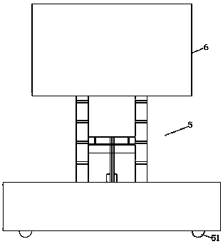
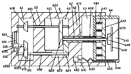
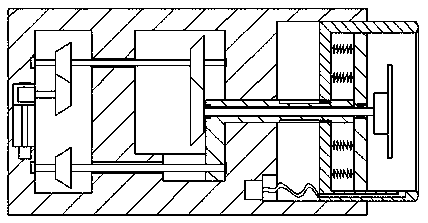
[0021] Such as Figure 1-Figure 5 As shown, a dust remover of the present invention includes a guide rail type lift structure 5 and a dust removal device 6 arranged on the top of the guide rail type lift structure 5 , and a storage tank 63 is provided inside the right side of the dust removal device 6 , The storage tank 63 is slidably connected with a dust collection cover 64, the inside of the dust collection cover 64 is provided with a dust removal cavity 641, and the inside of the dust removal device 6 on the left side of the storage tank 63 is provided with a conduction cavity 62. A first partition plate 66 is provided between the conduction chamber 62 and the storage tank 63, and a drive chamber 61 is provided inside the dust removal device 6 on the left side of the conduction chamber 62, and the drive chamber 61 is connected to the conduction chamber 62. A second partition plate 65 is provided between the cavities 62, a first sliding groove 623 is provided at the inner b...


PUM


Abstract

The invention discloses a dust remover. The dust remover comprises a guide rail type lifting structure and a dust removal device arranged on the top of the guide rail lifting structure, a storage tank is formed inside the right side face of the dust removal device, a dust collecting cover is connected to the storage tank in a sliding and matched mode, a dust removal cavity is formed inside the dust collecting cover, a conducting cavity is formed in the portion, at the left side of the storage tank, inside the dust removal device, a second partition panel is arranged between a driven cavity and the storage tank, a first sliding tank is formed in the bottom inside the conducting cavity, a transmission rod arranged to extend to the left side and the right side is connected into the first partition panel in a sliding and matched mode, the right extending section of the transmission rod extends into the storage tank and penetrates through the dust collecting cover to extend into the dust removal cavity, a bearing plate is fixedly arranged at the transmission rod right side extending tail end, and a first via hole arranged to extend left and right is formed inside the transmission rod. The dust remover is simple in structure, reasonable in design, capable of reducing the occupied space and low in manufacturing and maintenance cost.

Description

technical field [0001] The invention relates to the technical field of environmental protection, and relates to a dust collector. Background technique [0002] In the process of production operations, a large amount of dust is often produced, which not only aggravates environmental pollution, but also seriously endangers the health of workers. At present, many manufacturers lack dust control equipment. The dust removal equipment on the market is large in size, heavy in weight, and expensive. , is difficult to be widely accepted for use. Contents of the invention [0003] The technical problem to be solved by the present invention is to provide a dust collector, which can solve the above-mentioned problems in the prior art. [0004] The present invention is achieved through the following technical solutions: a dust remover of the present invention includes a guide rail type lifting structure and a dust removal device arranged on the top of the guide rail type lifting struc...

Claims


Application Information

Patent Timeline
Patent Type & Authority Patents(China)
IPC IPC(8): B01D45/14B01D45/02
CPCB01D45/02B01D45/14
Inventor 吴芉
Owner 安徽华裕重工有限公司
Why Eureka
Try Eureka