Practical dust remover

A dust collector and practical technology, applied in chemical instruments and methods, dispersed particle separation, separation methods, etc., can solve problems such as harm to workers' health, large size of dust removal equipment, and difficulty in being widely used, and reduce equipment investment and structure. The effect of simplicity, manufacturing costs and low maintenance costs

Inactive Publication Date: 2018-05-29
成都中创空间科技有限公司
View PDF3 Cites 0 Cited by
  • Summary
  • Abstract
  • Description
  • Claims
  • Application Information

AI Technical Summary

Problems solved by technology

[0002] In the process of production operations, a large amount of dust is often produced, which not only aggravates environmental pollution, but also seriously endangers the health of workers....

Method used


Image

  • Practical dust remover
  • Practical dust remover
  • Practical dust remover

Examples


Embodiment Construction

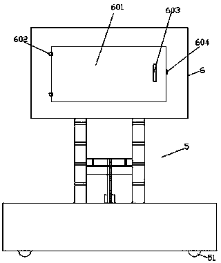
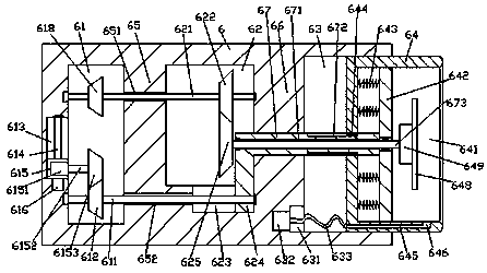
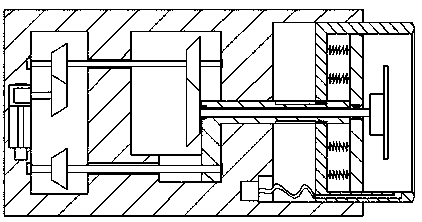
[0022] Such as Figure 1-Figure 5 As shown, a practical dust collector of the present invention includes a guide rail type lifting and lowering structure 5 and a dust removal device 6 arranged on the top of the guide rail type lifting and lowering structure 5, and a storage slot is provided inside the right side of the dust removal device 6 63. The storage slot 63 is connected with a dust collecting sleeve 64 in a sliding fit, the dust collecting sleeve 64 is provided with a dust removal cavity 641 inside, and the dust removal device 6 on the left side of the storage groove 63 is provided with a conducting cavity 62 inside, A first partition plate 66 is provided between the conductive cavity 62 and the storage slot 63, and the dust removal device 6 on the left side of the conductive cavity 62 is provided with a driving cavity 61, and the driving cavity 61 is A second partition plate 65 is provided between the conduction cavity 62, a first sliding groove 623 is provided at the b...


PUM


Abstract

The invention discloses a practical dust remover. The dust remover comprises a guiderail type lifting structure and a dust removing device arranged at the top of the guiderail type lifting structure and is characterized in that a storage groove is arranged inside the right side of the dust removing device, a dust collecting sleeve is connected to the storage groove in a slide fit manner, a dust removing cavity is arranged inside the dust collecting sleeve, a transmission cavity is arranged inside the dust removing device on the left of the storage groove, a first partition is arranged betweenthe transmission cavity and the storage groove, a drive cavity is arranged inside the dust removing device on the left of the transmission cavity, a second partition is arranged between the drive cavity and the transmission cavity, a first slide groove is arranged in the inner bottom of the transmission cavity, a transmission rod extending leftwards and rightwards is connected into the first partition in a slide fit manner, the rightward extending section of the transmission rod extends into the storage groove, penetrates the dust collecting sleeve and extends into the dust removing cavity, asupport plate is fixedly arranged at the tail of the rightward extending section of the transmission rod, and a first via hole extending leftwards and rightwards is arranged inside the transmission rod. The dust remover is simple in structure, reasonable in design, capable of reducing space occupation and low in manufacturing and maintenance cost.

Description

Technical field [0001] The invention relates to the technical field of environmental protection, and is a practical dust collector. Background technique [0002] In the process of production operations, a large amount of dust is often generated, which not only aggravates environmental pollution, but also seriously endangers the health of workers. At present, many manufacturers lack equipment for dust control. The dust removal equipment on the market is large, heavy, and expensive. , It is difficult to be widely accepted and used. Summary of the invention [0003] The technical problem to be solved by the present invention is to provide a practical dust remover, which can solve the above-mentioned problems in the current technology. [0004] The present invention is realized through the following technical solutions: a practical dust remover of the present invention includes a guide rail type lifting and lowering structure and a dust removal device arranged on the top of the guide r...

Claims


Application Information

Patent Timeline
IPC IPC(8): B01D45/12B01D45/02
CPCB01D45/12B01D45/02
Inventor 吴芉
Owner 成都中创空间科技有限公司
Why Eureka
Try Eureka