
A New Type of Common Rail Injector

A technology of common rail injectors and injectors, applied in fuel injection devices, machines/engines, charging systems, etc. The economy of the fuel system and other issues can be avoided to control the fluctuation of the lift of the piston, that is, the needle valve, to maintain the pressure, and to improve the performance.

Active Publication Date: 2019-09-03
CHINA FIRST AUTOMOBILE
View PDF6 Cites 0 Cited by
  • Summary
  • Abstract
  • Description
  • Claims
  • Application Information

AI Technical Summary

Problems solved by technology

This part of the fuel has a high pressure, and the energy is completely transformed into heat, resulting in an increase in the temperature of the low-pressure oil circuit in the injector, which in turn affects the stability and reliability of the injector.
With the increase of the injection pressure, the dynamic oil return of the control chamber is also increasing, which will increase the energy consumption of the fuel supply pump, reduce the economy of the fuel system, and limit the increase of the injection pressure of the common rail system.

Method used


Image

  • A New Type of Common Rail Injector
  • A New Type of Common Rail Injector

Examples


Embodiment Construction

[0016] The present invention is described in further detail now in conjunction with accompanying drawing. These drawings are all simplified schematic diagrams, which only illustrate the basic structure of the present invention in a schematic manner, so they only show the configurations related to the present invention.

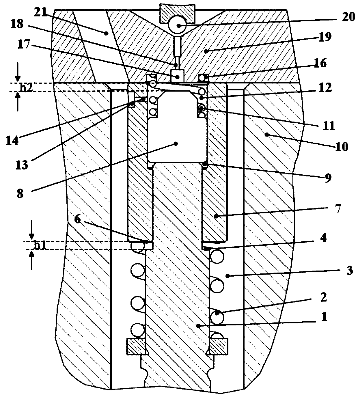
[0017] Such as figure 1 As shown, a new type of common rail injector includes injector body 10, orifice plate 19, control piston 1, floating block 8, and floating sleeve 7; the bottom of orifice plate 19 and injector body 10 form a high-pressure oil chamber A 3. The control piston 1, the floating block 8, the floating sleeve 7, the support spring 11, and the preload spring 2 are all located in the high-pressure oil chamber A 3; the orifice 19 is provided with an oil return passage 17, and the oil return passage 17 has an outlet The oil throttle hole 18, the oil return oil passage 17 and the low pressure oil passage are opened or closed by the sealing surface ...


PUM


Abstract

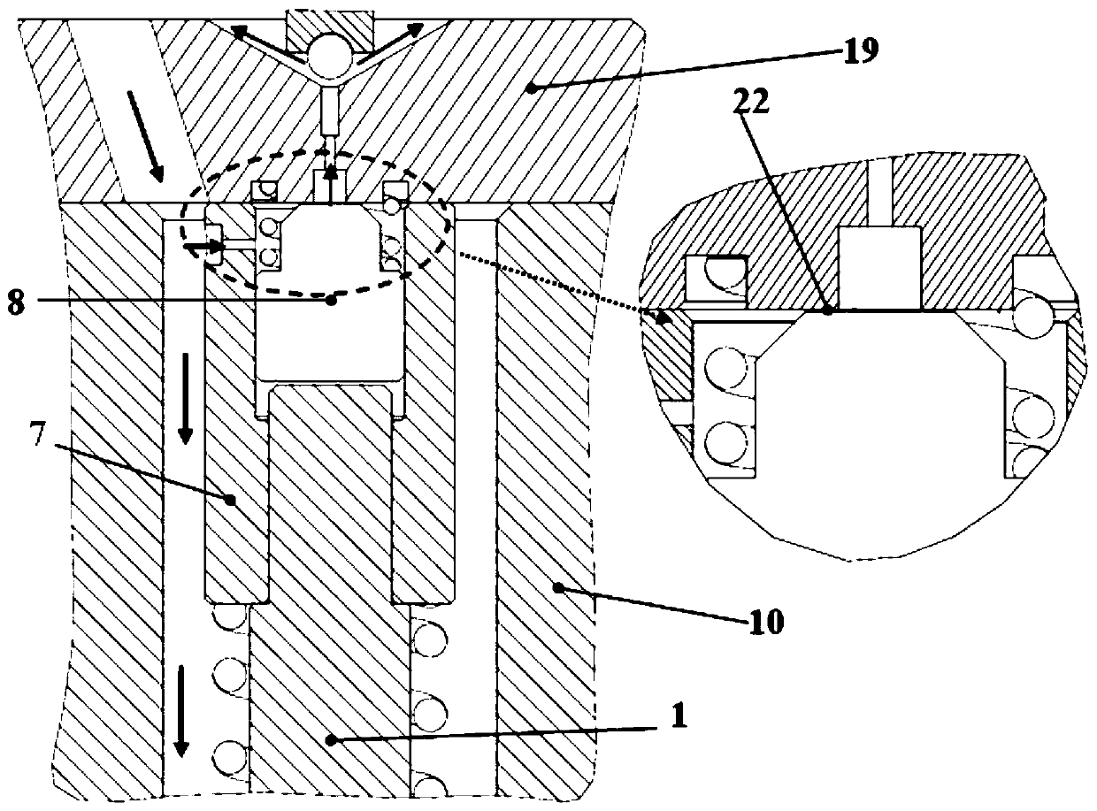
The invention discloses a novel common rail injector. The novel common rail injector is characterized in that a floating block and the top of a control piston are arranged in a floating bushing; one end of the floating bushing is connected to the bottom of a hole plate, and the other end is connected with a preloaded spring; when oil is sprayed from the injector, a throttling annular zone is formed between the floating block and the bottom surface of the hole plate to generate a flowing throttling flow, so that dynamic return oil of the injector is greatly reduced, and the power loss of an oil feed pump is reduced; meanwhile the clearance h1 between a boss at the top of the control piston and the bottom of the floating bushing is smaller than the clearance h2 between the floating block and the bottom of the hole plate, the floating block is in a complete floating state after the control piston ascends, the throttling annular clearance between the top of the floating block and the bottom surface of the hole plate is adjusted through hydraulic balance, the cavity pressure is stably maintained and controlled, and the performance of the injector is improved; as the clearance h1 is smaller than the clearance h2, the boss of the control piston is always in contact with the bottom of the floating bushing during the cavity pressure control adjustment process, and unstable oil injection of the injector due to lift range fluctuation of the control piston and the needle valve caused by floating adjustment on the floating block is avoided.

Description

technical field [0001] The invention belongs to the field of fuel injection systems for internal combustion engines, in particular to a novel common rail fuel injector. Background technique [0002] A typical common rail injector forms a control chamber between the control piston and the orifice plate (such as patent CN201080061266.7), or the control chamber is composed of the control piston, injector body and orifice plate (such as patent CN200510134109.5), through The solenoid valve controls the establishment and release of fuel pressure in the control chamber, thereby controlling the pressure difference between the piston and the needle valve, and realizing the control of the fuel injection process. And the control chamber has an oil inlet orifice and an oil outlet orifice, the oil inlet orifice is connected with the high pressure oil passage, and the oil outlet orifice is connected with the low pressure oil passage. Because the fuel injector is in the process of fuel in...

Claims


Application Information

Patent Timeline
Patent Type & Authority Patents(China)
IPC IPC(8): F02M47/02F02M61/10F02M61/16
Inventor 郭立新杨鹿周禛缪雪龙
Owner CHINA FIRST AUTOMOBILE
Learn More